background image

Limited Warranty 

“Products manufactured by CSI are warranted by CSI to be free from defects in 

materials and workmanship under normal use and service for twelve months 

from the date of shipment unless otherwise specified in the corresponding 

product manual. (Product manuals are available for review online at 

www.campbellsci.com

.) Products not manufactured by CSI, but that are resold 

by CSI, are warranted only to the limits extended by the original manufacturer. 

Batteries, fine-wire thermocouples, desiccant, and other consumables have no 

warranty. CSI’s obligation under this warranty is limited to repairing or 

replacing (at CSI’s option) defective Products, which shall be the sole and 

exclusive remedy under this warranty. The Customer assumes all costs of 

removing, reinstalling, and shipping defective Products to CSI. CSI will return 

such Products by surface carrier prepaid within the continental United States of 

America. To all other locations, CSI will return such Products best way CIP 

(port of entry) per Incoterms ® 2010. This warranty shall not apply to any 

Products which have been subjected to modification, misuse, neglect, improper 

service, accidents of nature, or shipping damage. This warranty is in lieu of all 

other warranties, expressed or implied. The warranty for installation services 

performed by CSI such as programming to customer specifications, electrical 

connections to Products manufactured by CSI, and Product specific training, is 

part of CSI's product warranty. 

CSI EXPRESSLY DISCLAIMS AND 

EXCLUDES ANY IMPLIED WARRANTIES OF MERCHANTABILITY 

OR FITNESS FOR A PARTICULAR PURPOSE

CSI hereby disclaims, 

to the fullest extent allowed by applicable law, any and all warranties and 

conditions with respect to the Products, whether express, implied or 

statutory, other than those expressly provided herein.

” 


Summary of Contents for COM220

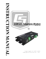
Page 1: ...INSTRUCTION MANUAL COM220 Telephone Modem Revision 3 15 C o p y r i g h t 1 9 9 7 2 0 1 5 C a m p b e l l S c i e n t i f i c I n c ...

Page 2: ......

Page 3: ...ducts to CSI CSI will return such Products by surface carrier prepaid within the continental United States of America To all other locations CSI will return such Products best way CIP port of entry per Incoterms 2010 This warranty shall not apply to any Products which have been subjected to modification misuse neglect improper service accidents of nature or shipping damage This warranty is in lieu...

Page 4: ...ng container Campbell Scientific s shipping address is CAMPBELL SCIENTIFIC INC RMA _____ 815 West 1800 North Logan Utah 84321 1784 For all returns the customer must fill out a Statement of Product Cleanliness and Decontamination form and comply with the requirements specified in it The form is available from our web site at www campbellsci com repair A completed form must be either emailed to repa...

Page 5: ...fore beginning work Wear a hardhat and eye protection and take other appropriate safety precautions while working on or around tripods and towers Do not climb tripods or towers at any time and prohibit climbing by other persons Take reasonable precautions to secure tripod and tower sites from trespassers Use only manufacturer recommended parts materials and tools Utility and Electrical You can be ...

Page 6: ......

Page 7: ...onnecting to a Surge Protector 8 4 Modem Settings 9 5 Troubleshooting 10 Appendices A Changing COM220 Settings A 1 A 1 DIP Switch Settings A 1 A 2 Hayes AT Commands A 2 A 3 Downloading a New Operating System to the COM220 A 6 A 4 Program Examples A 7 A 4 1 ModemCallback Example for CR1000 A 7 A 4 2 DialModem Example for CR1000 A 8 A 4 3 P97 Instruction for CR10X A 9 A 4 4 Example Programs for Data...

Page 8: ... surge suppressor wiring 8 3 4 Side view of surge suppressor wiring 9 A 1 COM220 to computer connection A 3 A 2 Device Configuration screen A 4 A 3 Terminal Emulator screen in Device Configuration A 5 A 4 Send OS screen in Device Configuration A 7 B 1 CS I O pinout B 1 Tables 1 1 Default DIP Switch Settings 2 3 1 Dataloggers that Require Direct 12 Vdc Connection to COM220 4 A 1 Selecting ME Baud R...

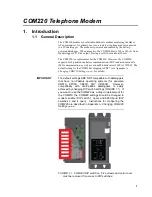
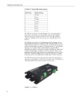
Page 9: ...aud rates 9600 to 115200 The default setting for the COM220 at shipping is SDC7 see Appendix A Changing COM220 Settings p A 1 for details The default settings ARE NOT compatible with dataloggers that have non PakBus operating systems for example CR510 CR10X CR23X CR7 CR5000 However compatibility with non PakBus dataloggers is easily achieved by changing DIP switch settings FIGURE 1 1 If you want t...

Page 10: ...back instruction or the DialSequence and DialModem instructions to program the datalogger to originate a call to the computer For non PakBus dataloggers for example CR510 CR10X CR23X and older PakBus dataloggers for example CR10XPB CR23XPB CR510PB use Instruction 97 to program the datalogger to originate a call to the computer Refer to your datalogger manual and LoggerNet Help files for detailed d...

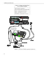
Page 11: ...x 2 6 in Weight 0 16 kg 0 35 lb 3 Installation The COM220 is designed to be used with standard analog telephone lines It will not work with a digital telephone line Connection to telephone company provided coin service central office implemented systems is prohibited Connection to party line service is subject to state tariffs 3 1 Connecting to Datalogger Connect the cable from the telephone RJ11C...

Page 12: ...aloggers that Require Direct 12 Vdc Connection to COM220 CR10 X with silver wiring panel CR10 X with black CR10 wiring panel pn 8032 21X L serial number 13 442 or lower CR500 serial number 1764 or lower CR7 CR700X serial number 2778 or lower FIGURE 3 1 CR1000 and COM220 using remote telephone line 4 ...

Page 13: ...round terminal GND on the COM220 and to the enclosure s earth ground connection If the site does not have a grounded enclosure connect the ground wire directly to an earth ground connection The datalogger ground should also be tied to the earth ground see FIGURE 3 1 and FIGURE 3 2 The modem must be grounded for its transient protection to work CAUTION 14 AWG Ground Wire Red 12V 14 AWG Ground Wire ...

Page 14: ...twork map and select the correct ComPort Connection for your modem Click on the PhoneBase in your network map Select your PC modem from the drop down list or add it using the Edit Modem Database dialog box Set the Maximum Baud Rate appropriate for your modem and datalogger Click on the PhoneModem in your network map Enter the COM220 s analog phone number If your datalogger is a PakBus datalogger c...

Page 15: ...mple programs for both a router datalogger and a remote datalogger communicating by telephone to MD485 or telephone to radio 3 5 Telephone Service If you have any questions about your telephone line such as how many pieces of equipment you can connect to it the telephone company will provide this information upon request If the telephone company requests information concerning the equipment which ...

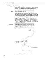
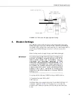
Page 16: ...t plastic body DC breakdown at 100 V sec is 300 to 500 V DC extinguishing at 52 V 135 V and 150 V is less than 150 ms FIGURE 3 3 and FIGURE 3 4 show the wiring for connecting the surge suppressor Color coding of wires may vary The important consideration is to follow tip all the way through and ring all the way through Getting wires crossed typically does not damage anything The phone line just wi...

Page 17: ...510 CR10X CR23X CR7 and CR5000 However compatibility with non PakBus dataloggers is easily achieved by changing DIP switch settings FIGURE 1 1 If you want to use the COM220 as a drop in replacement for the COM210 the COM220 settings should be changed to modem enable DIP switch 1 open and 9600 baud DIP switches 3 and 4 open Instructions for configuring the COM220 are described in Appendix A Changin...

Page 18: ...n that the COM220 is tested and approved for all foreign countries CCITT is an international consultative committee that sets international communications usage standards V 32 and V 22 are CCITT standards that the COM220 meets 5 Troubleshooting When the Campbell Scientific software cannot establish a link to a remote datalogger that is connected to a COM220 check the following 1 Verify that the mo...

Page 19: ...uter Even if a program is minimized in windows it may put a lock on a COM port Some notebook computers do not automatically activate the COM ports Verify that the COM port you are using is activated 9 Use the Low Level Log in the Campbell Scientific software LoggerNet Status Monitor Tools Log Tool View View I O Low Level Log to see connection progress while a link is being established Assuming the...

Page 20: ...rmed by Campbell Scientific Inc or an authorized agent of Campbell Scientific Inc For assistance in installation or troubleshooting or for repairs contact Campbell Scientific Campbell Scientific Inc 815 West 1800 North Logan Utah 84321 1784 Telephone 435 227 9000 Fax 435 227 9001 Website www campbellsci com 12 ...

Page 21: ...witch settings to take effect This is done by removing the 9 pin connector for about 5 s As with other devices if you leave the power off for too short a time you may get unexpected results DIP Switches 1 and 2 SDC or ME The COM220 supports synchronous device communication SDC and modem enable ME communication Switch 1 selects between SDC and ME If switch 1 is open ME mode is selected If switch 1 ...

Page 22: ...in configuration mode The COM220 can be configured using an SC532 or SC532A with a 12 Vac adapter pn 15966 and Device Configuration Utility version 1 6 or newer and Hayes AT commands see below A 2 Hayes AT Commands To configure the COM220 with Hayes AT commands you will need the Campbell Scientific Device Configuration Utility version 1 6 or newer and an SC532 or SC532A device An SC12 cable must b...

Page 23: ...RS232 cable Leave the COM220 modem disconnected for now 3 Run Device Configuration Utility version 1 6 or newer 4 Select COM220 from the Device Configuration Utility menu FIGURE A 2 5 Make sure the appropriate serial port is selected on the left panel of the Device Configuration Utility window and click on the connect button 6 Once you have clicked on the connect button connect the peripheral port...

Page 24: ...to the COM220 7 Follow the instructions that appear in the terminal emulator screen FIGURE A 3 8 Be sure to save all new commands before exiting by entering 5 and pressing Enter 9 When finished return DIP switch 8 on the COM220 to its open position FIGURE A 2 Device Configuration screen NOTE A 4 ...

Page 25: ...mmands For example to change the default number of rings from 1 to 3 the command is ATS0 2 the default is 1 ring as the MPU sends ATS0 1 by default to the modem module To turn the speaker off the command is ATM0 For command changes to be effective you MUST press Enter after typing the command and you MUST press 5 to save the new command before disconnecting or exiting set up COMMANDS TO CHANGE DEF...

Page 26: ...Leave the modem disconnected for now 2 Make sure that you have the appropriate serial port selected in the left panel of the Device Configuration Utility window 3 Click the Start button 4 In the resulting file open dialogue box that appears select the file that should be sent as the modem s operating system Do not attempt to load any operating system other than that designed for the COM220 modem 5...

Page 27: ...s The ModemCallBack instruction assumes that LoggerNet resides at the phone number and that callback is enabled in LoggerNet Setup both for the comport and for the datalogger Public PTemp batt_volt Count Result as Long Const Abort 0 False DataTable Test5 1 1 DataInterval 0 0 Sec 10 Sample 1 batt_volt FP2 Minimum 1 batt_volt FP2 0 False Maximum 1 batt_volt FP2 False False Sample 1 PTemp FP2 Minimum...

Page 28: ... PTemp TCvalue_F dummy Public RespStrng DialSuccess AccumDialFails as LONG DataTable DC1 1 1000 DataInterval 0 0 Sec 10 Sample 1 PTemp FP2 Sample 1 TCvalue_F FP2 Sample 1 DialSuccess FP2 EndTable DialSequence 4094 Establishes a phone connection if there isn t one already DialSuccess DialModem ComSDC7 115200 5551212 Param 2 baud rate setting affects sdc bit rate Param 4 allows OS to accept any list...

Page 29: ...s using some other modem that he knows has a different response string than those listed above A 4 3 P97 Instruction for CR10X Instruction 97 is a Program Control instruction that makes the following types of calls Datalogger calls a computer to send data Datalogger calls a voice phone using our voice synthesized modem Datalogger calls a remote datalogger to retrieve its input locations Instructio...

Page 30: ...t Flag 8 High 4 End P95 5 Batt Voltage P10 1 1 Loc BatVolt measure battery voltage 6 Internal Temperature P17 1 2 Loc TEMP_PANL measure panel temperature 7 If time is P92 final storage every 10 seconds 1 0 Minutes Seconds into a 2 10 Interval same units as above 3 10 Set Output Flag High Flag 0 8 Real Time P77 1 111 Day Hour Minute Seconds midnight 0000 place a time stamp 9 Sample P70 1 1 Reps 2 1...

Page 31: ...e The remote datalogger s PakBusAddress 1 In addition the RF401s or MD485s are set for CSDC8 see the RF401 or MD485 manual for directions on configuring these devices Program for CR1000 Router Router program for data callback via router w phone link to LoggerNet Phone to MD485 or RF401 w DL at Base Router PakBus Address 2 IsRouter 1 BeaconSDC8 30 to discover Remote DL which has PBA 1 Router COM220...

Page 32: ...er Public batt_volt Result Public PTemp TCvalue_F dummy Public RespStrng DialSuccess DataTable DC1 1 1000 DataInterval 0 0 Sec 10 Sample 1 PTemp FP2 Sample 1 TCvalue_F FP2 Sample 1 DialSuccess FP2 EndTable BeginProg Scan 2 Min 3 0 PanelTemp PTemp 250 Battery Batt_volt dummy 0 TCDiff TCvalue_F 1 mV2_5C 1 TypeT PTemp True 0 250 1 8 32 SendVariables Result ComSDC7 2 4094 0000 3500 Public Callback dum...

Page 33: ... internal line drivers for Ring and RX Data output signals 2 input Ground 3 output Ring A logic high signifies a ring signal has been detected 4 output RX Data Serial data from COM220 5 input Modem Enable A logic high internally switches power to the modem A logic low internally shuts off power to the modem 6 input Serial Device Enable A logic high disables communication with the modem without rem...

Page 34: ...Appendix B CS I O Connection B 2 ...

Page 35: ... is continuously powered but draws less than 2 µA The ring signal is passed on to the datalogger through an opto coupler The datalogger responds to a ring by raising the modem enable line which internally switches the regulated 5 V supply to the rest of the modem s circuitry The modem then answers and remains off hook until it loses the carrier or the datalogger lowers the modem enable line The da...

Page 36: ...Appendix C Theory of Operation C 2 ...

Page 37: ...t has been tested and found to comply with the limits for a Class B computing device pursuant to Subpart J of Part 15 of FCC Rules which are designed to provide reasonable protection against such interference when operated in a COMMERCIAL ENVIRONMENT Operation of this equipment in a residential area may cause interference to radio and television reception The operator must take whatever measures a...

Page 38: ...Appendix D FCC Warning to Users of Class B Computing Devices D 2 ...

Page 39: ...coordinated by a representative designated by the supplier Any repairs or alterations made by the user to this equipment or equipment malfunctions may give the telecommunications company cause to request the user to disconnect the equipment Users should ensure for their own protection that the electrical ground connections of the power utility telephone lines and internal metallic water pipe syste...

Page 40: ...Appendix E IC Information E 2 ...

Page 41: ......

Page 42: ...om br Campbell Scientific Canada Corp CSC 14532 131 Avenue NW Edmonton AB T5L 4X4 CANADA www campbellsci ca dataloggers campbellsci ca Campbell Scientific Centro Caribe S A CSCC 300 N Cementerio Edificio Breller Santo Domingo Heredia 40305 COSTA RICA www campbellsci cc info campbellsci cc Campbell Scientific Ltd CSL Campbell Park 80 Hathern Road Shepshed Loughborough LE12 9GX UNITED KINGDOM www ca...

Reviews: