Section 7. Installation
Note
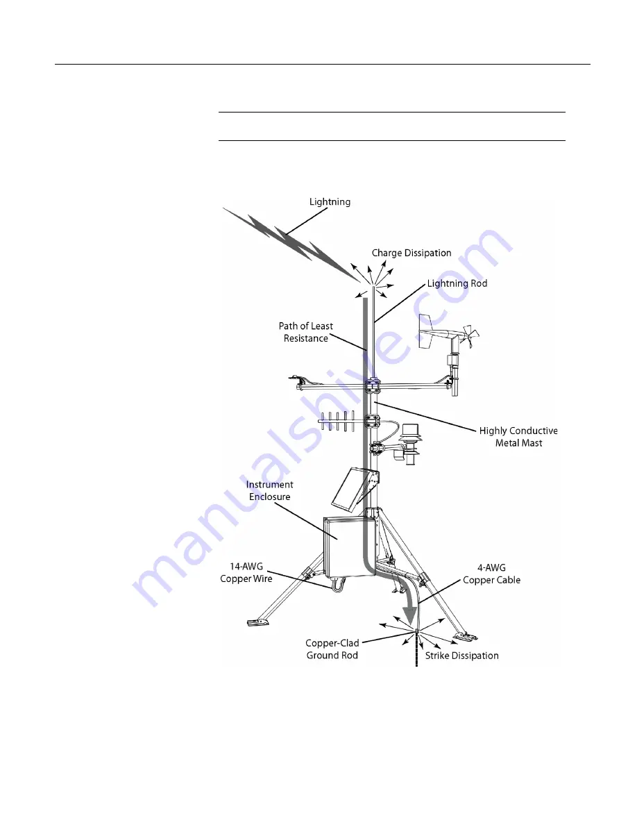
Lightning strikes may damage or destroy the CR1000 and associated
sensors and power supplies.
In addition to protections discussed in
,
use of a simple lightning rod and low-
resistance path to earth ground is adequate protection in many installations. .
Figure 34. Lightning-Protection Scheme
7.6.2 Single-Ended Measurement Reference
Low-level, single-ended voltage measurements (<200 mV) are sensitive to ground
potential fluctuation due to changing return currents from
12V
,
SW12
,
5V
, and
C1
–
C8
terminals. The CR1000 grounding scheme is designed to minimize these
108
Summary of Contents for CR1000
Page 2: ......
Page 4: ......
Page 6: ......
Page 32: ......
Page 36: ......
Page 38: ......
Page 40: ......
Page 60: ...Section 4 System Quickstart Figure 16 PC200W View Line Graph 60 ...
Page 96: ......
Page 98: ...98 ...
Page 302: ......
Page 453: ...Section 8 Operation Figure 115 Using the Keyboard Display 453 ...
Page 456: ...Section 8 Operation Figure 118 Real Time Custom 456 ...
Page 457: ...Section 8 Operation 8 8 1 3 Final Memory Tables Figure 119 Final Memory Tables 457 ...
Page 458: ...Section 8 Operation 8 8 2 Run Stop Program Figure 120 Run Stop Program 458 ...
Page 460: ...Section 8 Operation Figure 122 File Edit 460 ...
Page 461: ...Section 8 Operation 8 8 4 PCCard Memory Card Display Figure 123 PCCard CF Card Display 461 ...
Page 478: ......
Page 506: ......
Page 536: ......
Page 636: ......
Page 642: ......
Page 644: ......
Page 676: ......
Page 677: ......


