Section 7. Installation
4. Follow the on-screen
OS Download Instructions
Pros/Cons
This is a good way to recover a CR1000 that has gone into an unresponsive state.
Often, an operating system can be loaded even if you are unable to communicate
with the CR1000 through other means.
Loading an operating system through this method will do the following:
1. Restore all CR1000 settings to factory defaults
2. Delete data in final storage
3. Delete data from and remove the USR drive
4. Delete program files stored on the datalogger
7.7.2.1.2 OS Update with DevConfig
This method is very similar to sending an OS as a program, with the exception
that you have to manually prepare the datalogger to accept the new OS.
How
1. Connect to the CR1000 with
Connect
or
DevConfig
2. Collect data
3. Transfer a
default.CR1
(p. 116)
program file to the CR1000 CPU: drive
4. Stop the current program and select the option to delete associated data (this
will free up SRAM memory allocated for data storage)
5. Collect files from the USR: drive (if applicable)
6. Delete the USR: drive (if applicable)
7. Send the new .obj OS file to the CR1000
8. Restart the previous program (default.CR1 will be running after OS compiles)
Pros/Cons
This method is preferred because the user must manually configure the datalogger
to receive an OS and thus should be cognizant of what is happening (loss of data,
program being stopped, etc.).
Loading an operating system through this method will do the following:
1. Preserve all CR1000 settings
2. Delete all data in final storage
3. Delete USR: drive
4. Stop current program deletes data and clears run options
5. Deletes data generated using the
CardOut()
or
TableFile()
instructions
7.7.2.1.3 OS Update with DevConfig
A send program command is a feature of
DevConfig
and other
datalogger support
software
(p. 654).
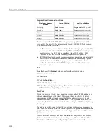
Location of this command in the software is listed in table
Program Send Command Locations
119
Summary of Contents for CR1000
Page 2: ......
Page 4: ......
Page 6: ......
Page 32: ......
Page 36: ......
Page 38: ......
Page 40: ......
Page 60: ...Section 4 System Quickstart Figure 16 PC200W View Line Graph 60 ...
Page 96: ......
Page 98: ...98 ...
Page 302: ......
Page 453: ...Section 8 Operation Figure 115 Using the Keyboard Display 453 ...
Page 456: ...Section 8 Operation Figure 118 Real Time Custom 456 ...
Page 457: ...Section 8 Operation 8 8 1 3 Final Memory Tables Figure 119 Final Memory Tables 457 ...
Page 458: ...Section 8 Operation 8 8 2 Run Stop Program Figure 120 Run Stop Program 458 ...
Page 460: ...Section 8 Operation Figure 122 File Edit 460 ...
Page 461: ...Section 8 Operation 8 8 4 PCCard Memory Card Display Figure 123 PCCard CF Card Display 461 ...
Page 478: ......
Page 506: ......
Page 536: ......
Page 636: ......
Page 642: ......
Page 644: ......
Page 676: ......
Page 677: ......


