Section 7. Installation
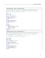
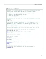
CRBasic Example 40.
FieldCal()
Zero
'This program example demonstrates the use of FieldCal() in calculating and applying a zero
'calibration. A zero calibration measures the signal magnitude of a sensor in a known zero
'condition and calculates the negative magnitude to use as an offset in subsequent
'measurements. It does not affect the multiplier.
'
'This program demonstrates the zero calibration with the following procedure:
' -- Simulate a signal from a relative-humidity sensor.
' -- Measure the 'sensor' signal.
' -- Calculate and apply a zero calibration.
'You can set up the simulation by loading this program into the CR1000 and interconnecting
'the following terminals with a jumper wire to simulate the relative-humidity sensor signal
'as follows:
'
Vx1
---
SE
1
'For the simulation, the initial 'sensor' signal is set automatically. Start the zero routine
'by setting variable CalMode = 1. When CalMode = 6 (will occur automatically after 10
'measurements), the routine is complete. Note the new value in variable RHOffset. Now
'enter the following millivolt value as the simulated sensor signal and note how the new
'offset is added to the measurement:
' SimulatedRHSignal = 1000
'NOTE: This program places a .cal file on the CPU: drive of the CR1000. The .cal file must
'be erased to reset the demonstration.
'DECLARE SIMULATED SIGNAL VARIABLE AND SET INITIAL MILLIVOLT SIGNAL MAGNITUDE
Public
SimulatedRHSignal =
100
'DECLARE CALIBRATION STANDARD VARIABLE AND SET PERCENT RH MAGNITUDE
Public
KnownRH = 0
'DECLARE MEASUREMENT RESULT VARIABLE.
Public
RH
'DECLARE OFFSET RESULT VARIABLE
Public
RHOffset
'DECLARE VARIABLE FOR FieldCal() CONTROL
Public
CalMode
'DECLARE DATA TABLE FOR RETRIEVABLE CALIBRATION RESULTS
DataTable
(CalHist,NewFieldCal,200)
SampleFieldCal
EndTable
BeginProg
'LOAD CALIBRATION CONSTANTS FROM FILE CPU:CALHIST.CAL
'Effective after the zero calibration procedure (when variable CalMode = 6)
LoadFieldCal
(true)
215
Summary of Contents for CR1000
Page 2: ......
Page 4: ......
Page 6: ......
Page 32: ......
Page 36: ......
Page 38: ......
Page 40: ......
Page 60: ...Section 4 System Quickstart Figure 16 PC200W View Line Graph 60 ...
Page 96: ......
Page 98: ...98 ...
Page 302: ......
Page 453: ...Section 8 Operation Figure 115 Using the Keyboard Display 453 ...
Page 456: ...Section 8 Operation Figure 118 Real Time Custom 456 ...
Page 457: ...Section 8 Operation 8 8 1 3 Final Memory Tables Figure 119 Final Memory Tables 457 ...
Page 458: ...Section 8 Operation 8 8 2 Run Stop Program Figure 120 Run Stop Program 458 ...
Page 460: ...Section 8 Operation Figure 122 File Edit 460 ...
Page 461: ...Section 8 Operation 8 8 4 PCCard Memory Card Display Figure 123 PCCard CF Card Display 461 ...
Page 478: ......
Page 506: ......
Page 536: ......
Page 636: ......
Page 642: ......
Page 644: ......
Page 676: ......
Page 677: ......

