Section 8. Operation
The magnitude of the frequency response of an analog integrator is a SIN(x)/x
shape, which has notches (transmission zeros) occurring at 1/(integer multiples) of
the integration duration. Consequently, noise at 1/(integer multiples) of the
integration duration is effectively rejected by an analog integrator. If reversing
the differential inputs or reversing the excitation is specified, there are two
separate integrations per measurement; if both reversals are specified, there are
four separate integrations.
Table 59.
Analog Measurement Integration
Integration Time (ms)
Integration Parameter
Argument
Comments
0 to 16000 µs
0 to 16000
250 µs is considered fast and
normally the minimum
16.667 ms
_60Hz
Filters 60 Hz noise
20 ms
_50Hz
Filters 50 Hz noise
Ac Power-Line Noise Rejection
Grid or mains power (50 or 60 Hz, 230 or 120 Vac) can induce electrical noise at
integer multiples of 50 or 60 Hz. Small analog voltage signals, such as
thermocouples and pyranometers, are particularly susceptible. CR1000 voltage
measurements can be programmed to reject (filter) 50 Hz or 60 Hz related noise.
Noise is rejected by using a signal integration time that is relative to the length of
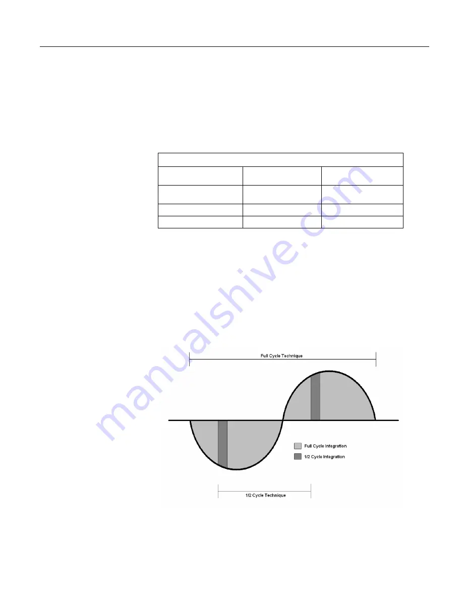
the ac noise cycle, as illustrated in the figure
Ac Power-Line Noise Rejection
Techniques
(p. 316).
FIGURE. Ac power line noise rejection techniques -- 8 10 30
Figure 83. Ac-Power Noise-Rejection Techniques
The CR1000 rejects ac power line noise on all voltage ranges except
mV5000
and
mV2500
by integrating the measurement over exactly one full ac cycle before
A-
316
Summary of Contents for CR1000
Page 2: ......
Page 4: ......
Page 6: ......
Page 32: ......
Page 36: ......
Page 38: ......
Page 40: ......
Page 60: ...Section 4 System Quickstart Figure 16 PC200W View Line Graph 60 ...
Page 96: ......
Page 98: ...98 ...
Page 302: ......
Page 453: ...Section 8 Operation Figure 115 Using the Keyboard Display 453 ...
Page 456: ...Section 8 Operation Figure 118 Real Time Custom 456 ...
Page 457: ...Section 8 Operation 8 8 1 3 Final Memory Tables Figure 119 Final Memory Tables 457 ...
Page 458: ...Section 8 Operation 8 8 2 Run Stop Program Figure 120 Run Stop Program 458 ...
Page 460: ...Section 8 Operation Figure 122 File Edit 460 ...
Page 461: ...Section 8 Operation 8 8 4 PCCard Memory Card Display Figure 123 PCCard CF Card Display 461 ...
Page 478: ......
Page 506: ......
Page 536: ......
Page 636: ......
Page 642: ......
Page 644: ......
Page 676: ......
Page 677: ......


