Section 8. Operation
Table 83.
Low-Level Ac Amplitude and Maximum Measured
Frequency
Ac mV (RMS)
Maximum Frequency
20
200
2000
5000
20
200
10,000
20,000
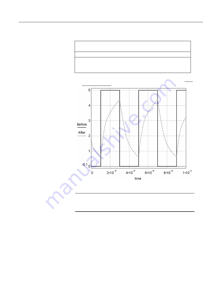
Figure 94. Amplitude reduction of pulse-count waveform (before and after
1 µs time-constant filter)
8.1.4 Period Averaging — Details
Related Topics:
• Period Averaging
— Specifications
•
Period Averaging — Overview
(p. 70)
•
Period Averaging — Details
(p. 360)
The CR1000 can measure the period of a signal on a
SE
terminal. The specified
number of cycles is timed with a resolution of 136 ns, making the resolution of
the period measurement 136 ns ns divided by the number of cycles chosen.
Low-level signals are amplified prior to a voltage comparator. The internal
voltage comparator is referenced to the programmed threshold. The threshold
parameter allows referencing the internal voltage comparator to voltages other
than 0 V. For example, a threshold of 2500 mV allows a 0 to 5 Vdc digital signal
to be sensed by the internal comparator without the need of any additional input
conditioning circuitry. The threshold allows direct connection of standard digital
360
Summary of Contents for CR1000
Page 2: ......
Page 4: ......
Page 6: ......
Page 32: ......
Page 36: ......
Page 38: ......
Page 40: ......
Page 60: ...Section 4 System Quickstart Figure 16 PC200W View Line Graph 60 ...
Page 96: ......
Page 98: ...98 ...
Page 302: ......
Page 453: ...Section 8 Operation Figure 115 Using the Keyboard Display 453 ...
Page 456: ...Section 8 Operation Figure 118 Real Time Custom 456 ...
Page 457: ...Section 8 Operation 8 8 1 3 Final Memory Tables Figure 119 Final Memory Tables 457 ...
Page 458: ...Section 8 Operation 8 8 2 Run Stop Program Figure 120 Run Stop Program 458 ...
Page 460: ...Section 8 Operation Figure 122 File Edit 460 ...
Page 461: ...Section 8 Operation 8 8 4 PCCard Memory Card Display Figure 123 PCCard CF Card Display 461 ...
Page 478: ......
Page 506: ......
Page 536: ......
Page 636: ......
Page 642: ......
Page 644: ......
Page 676: ......
Page 677: ......


