Section 8. Operation
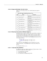
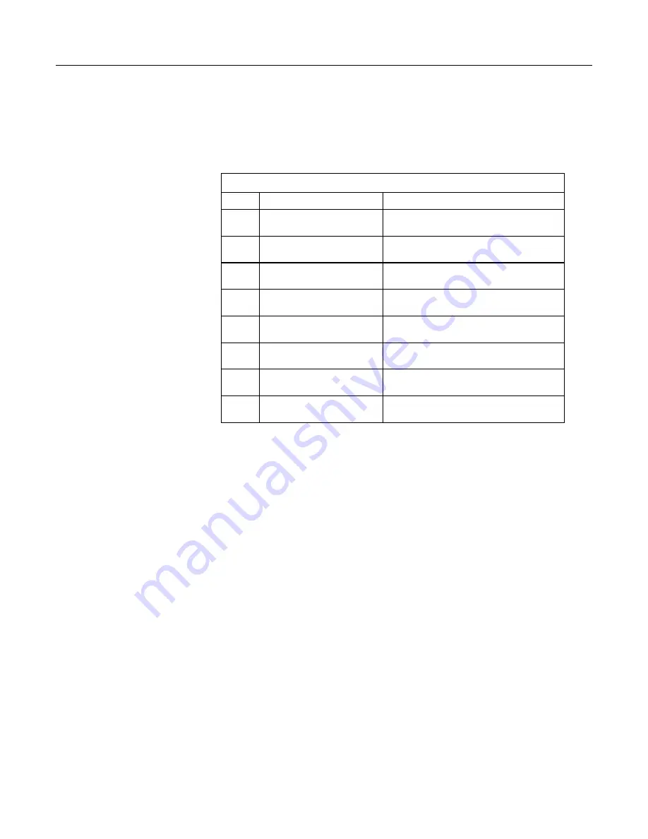
8.6.2.2.4 Supported Modbus Function Codes
Modbus protocol has many function codes. CR1000 commands support the
following.
Table 108.
Supported Modbus Function Codes
Code
Name
Description
01
Read coil/port status
Reads the on/off status of discrete output(s) in the
ModBusSlave
02
Read input status
Reads the on/off status of discrete input(s) in the
ModBusSlave
03
Read holding registers
Reads the binary contents of holding register(s) in
the ModBusSlave
04
Read input registers
Reads the binary contents of input register(s) in
the ModBusSlave
05
Force single coil/port
Forces a single coil/port in the ModBusSlave to
either on or off
06
Write single register
Writes a value into a holding register in the
ModBusSlave
15
Force multiple coils/ports
Forces multiple coils/ports in the ModBusSlave to
either on or off
16
Write multiple registers
Writes values into a series of holding registers in
the ModBusSlave
8.6.2.2.5 Reading Inverse-Format Modbus Registers
Some Modbus devices require reverse byte order words (CDAB vs. ABCD). This
can be true for either floating point, or integer formats. Since a slave CR1000
uses the ABCD format, either the master has to make an adjustment, which is
sometimes possible, or the CR1000 needs to output reverse-byte order words. To
reverse the byte order in the CR1000, use the
MoveBytes()
instruction as shown
in the sample code below.
for
i = 1
to
k
MoveBytes
(InverseFloat(i),2,Float(i),0,2)
MoveBytes
(InverseFloat(i),0,Float(i),2,2)
next
In the example above,
InverseFloat(i)
is the array holding the inverse-byte
ordered word (CDAB). Array
Float(i)
holds the obverse-byte ordered word
(ABCD).
See the appendix
Endianness
(p. 643).
8.6.2.3 Troubleshooting (Modbus)
Test Modbus functions on the CR1000 with third party Modbus software. Further
information is available at the following links:
•
www.simplyModbus.ca/FAQ.htm
•
www.Modbus.org/tech.php
•
www.lammertbies.nl/comm/info/modbus.html
415
Summary of Contents for CR1000
Page 2: ......
Page 4: ......
Page 6: ......
Page 32: ......
Page 36: ......
Page 38: ......
Page 40: ......
Page 60: ...Section 4 System Quickstart Figure 16 PC200W View Line Graph 60 ...
Page 96: ......
Page 98: ...98 ...
Page 302: ......
Page 453: ...Section 8 Operation Figure 115 Using the Keyboard Display 453 ...
Page 456: ...Section 8 Operation Figure 118 Real Time Custom 456 ...
Page 457: ...Section 8 Operation 8 8 1 3 Final Memory Tables Figure 119 Final Memory Tables 457 ...
Page 458: ...Section 8 Operation 8 8 2 Run Stop Program Figure 120 Run Stop Program 458 ...
Page 460: ...Section 8 Operation Figure 122 File Edit 460 ...
Page 461: ...Section 8 Operation 8 8 4 PCCard Memory Card Display Figure 123 PCCard CF Card Display 461 ...
Page 478: ......
Page 506: ......
Page 536: ......
Page 636: ......
Page 642: ......
Page 644: ......
Page 676: ......
Page 677: ......


