Section 8. Operation
8.6.3.14.7 Clock Functions — ClockSet Command
ClockSet
allows a web client to set the CR1000 real time clock.
ClockSet
takes
the form:
http://ip_address/?command=ClockSet&format=html&time=YYYY-MM-
DDTHH:MM:SS.MS
ClockSet
requires a minimum
.csipasswd
access level of
1
(all access allowed)
.
Table 115.
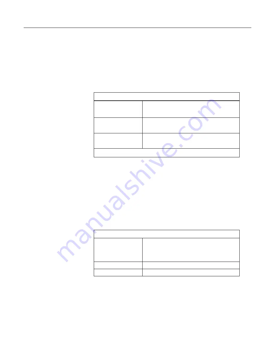
ClockSet API Command Parameters
uri
If this parameter is excluded, or if it is set to "datalogger"
(
uri=dl
) or an empty string (
uri=
), the command is sent to the
CR1000 web server.
1
format
Specifies the format of the response. The values
html
,
json
, and
xml
are valid. If this parameter is omitted, or if the value is
html
, empty, or invalid, the response is HTML.
time
Specifies the time to which the CR1000 real-time clock is set.
This value must conform to the format described for input time
stamps in the
Time Syntax
(p. 427)
section.
1
optionally specifies the URI for the
LoggerNet
source station to be set
Example:
http://192.168.24.106/?command=ClockSet&format=html&time=2012-9-
14T15:30:00.000
Response: sets the host CR1000 real time clock to 3:30 PM 14
September 2012.
ClockSet Response
The
ClockSet
format
parameter determines the format of the response. If a
format is not specified, the format defaults to HTML. For more detail concerning
data response formats, see the
Data File Formats
(p. 377)
section.
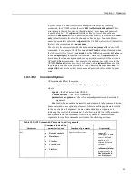
Responses contain three fields as described in the following table:
Table 116.
ClockSet API Command Response
outcome
1
— The clock was set
5
— Communication with the CR1000 failed
6
— Communication with the CR1000 is disabled
8
— An invalid URI was specified.
time
Specifies the value of the CR1000 clock before it was changed.
description
A string that describes the outcome code.
HTML Response
When
html
is entered in the
ClockSet
format
parameter, the response will be
HTML. Following are example responses.
439
Summary of Contents for CR1000
Page 2: ......
Page 4: ......
Page 6: ......
Page 32: ......
Page 36: ......
Page 38: ......
Page 40: ......
Page 60: ...Section 4 System Quickstart Figure 16 PC200W View Line Graph 60 ...
Page 96: ......
Page 98: ...98 ...
Page 302: ......
Page 453: ...Section 8 Operation Figure 115 Using the Keyboard Display 453 ...
Page 456: ...Section 8 Operation Figure 118 Real Time Custom 456 ...
Page 457: ...Section 8 Operation 8 8 1 3 Final Memory Tables Figure 119 Final Memory Tables 457 ...
Page 458: ...Section 8 Operation 8 8 2 Run Stop Program Figure 120 Run Stop Program 458 ...
Page 460: ...Section 8 Operation Figure 122 File Edit 460 ...
Page 461: ...Section 8 Operation 8 8 4 PCCard Memory Card Display Figure 123 PCCard CF Card Display 461 ...
Page 478: ......
Page 506: ......
Page 536: ......
Page 636: ......
Page 642: ......
Page 644: ......
Page 676: ......
Page 677: ......


