Section 4. System Quickstart
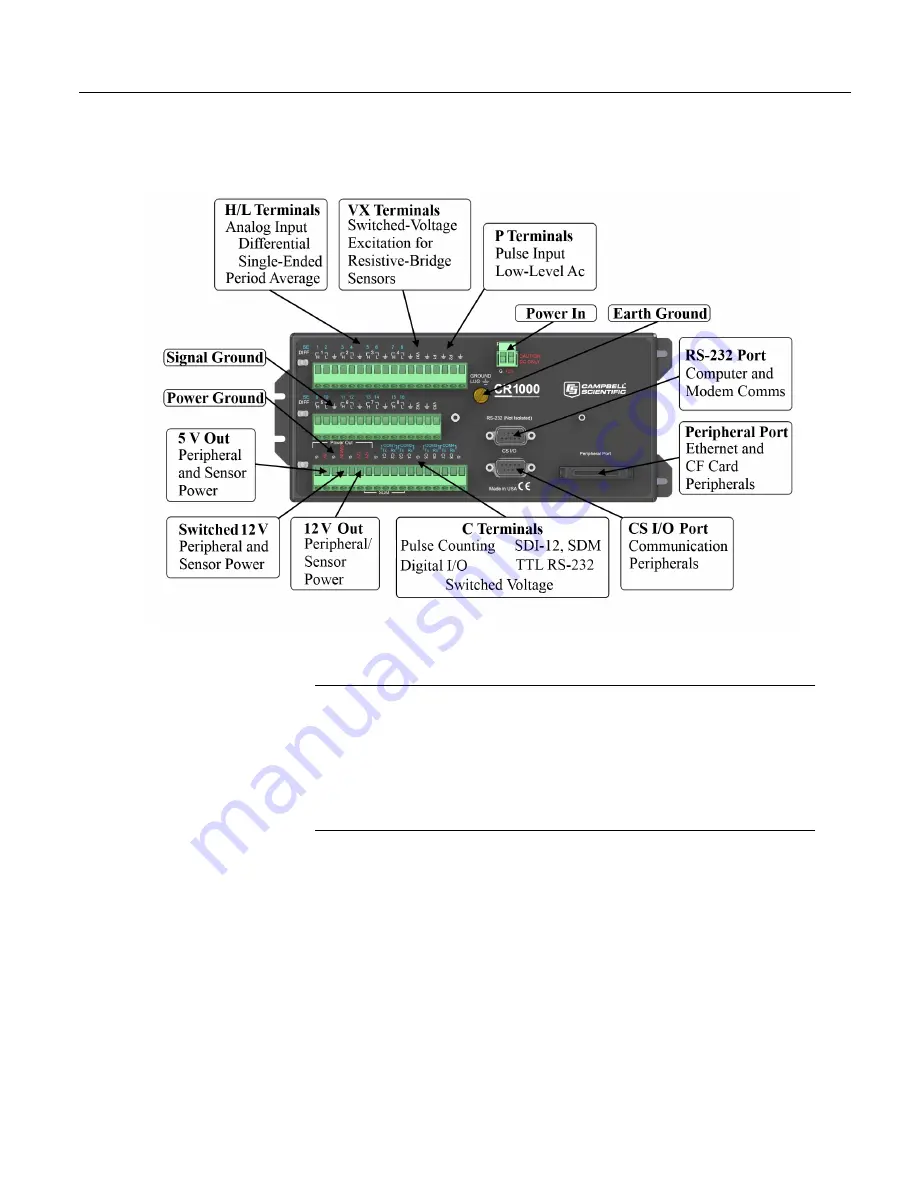
Figure 2. Wiring Panel
4.4
Power Supplies — Quickstart
Related Topics:
• Power Supplies
— Specifications
•
Power Supplies — Quickstart
(p. 44)
•
Power Supplies — Overview
(p. 85)
•
Power Supplies — Details
(p. 100)
•
Power Supplies — Products
(p. 657)
•
Power Sources
(p. 101)
•
Troubleshooting — Power Supplies
(p. 494)
The CR1000 requires a power supply. Be sure that any power supply components
match the specifications of the device to which they are connected. When
connecting power, first switch off the power supply, then make the connection
before switching the supply on.
The CR1000 is operable with power from 9.6 to 16 Vdc applied at the
POWER
IN
terminals of the green connector on the face of the wiring panel.
External power connects through the green
POWER IN
connector on the face of
the CR1000. The positive power lead connects to
12V
. The negative lead
44
Summary of Contents for CR1000
Page 2: ......
Page 4: ......
Page 6: ......
Page 32: ......
Page 36: ......
Page 38: ......
Page 40: ......
Page 60: ...Section 4 System Quickstart Figure 16 PC200W View Line Graph 60 ...
Page 96: ......
Page 98: ...98 ...
Page 302: ......
Page 453: ...Section 8 Operation Figure 115 Using the Keyboard Display 453 ...
Page 456: ...Section 8 Operation Figure 118 Real Time Custom 456 ...
Page 457: ...Section 8 Operation 8 8 1 3 Final Memory Tables Figure 119 Final Memory Tables 457 ...
Page 458: ...Section 8 Operation 8 8 2 Run Stop Program Figure 120 Run Stop Program 458 ...
Page 460: ...Section 8 Operation Figure 122 File Edit 460 ...
Page 461: ...Section 8 Operation 8 8 4 PCCard Memory Card Display Figure 123 PCCard CF Card Display 461 ...
Page 478: ......
Page 506: ......
Page 536: ......
Page 636: ......
Page 642: ......
Page 644: ......
Page 676: ......
Page 677: ......


