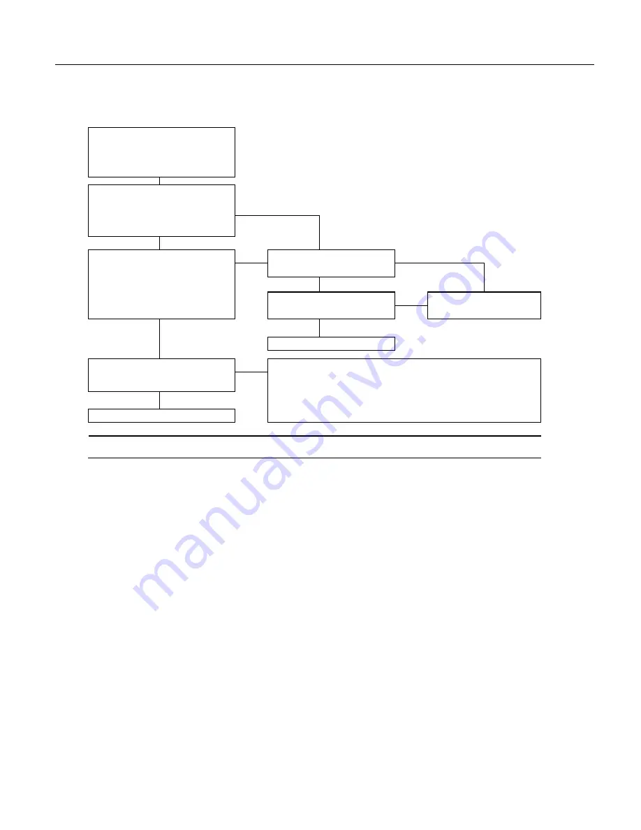
Section 10. Troubleshooting
Battery Test
If using a rechargeable power supply,
disconnect the charging source (i.e., solar panel
or ac transformer) from the battery pack. Wait
20 minutes before proceeding with this test.
Test Voltage at Charging Regulator
Set a voltmeter to read dc voltage as high as 15
V. Measure the voltage between a
12V
and
G
terminal on the charging regulator.
Is the voltage > 11.0 Vdc?
No
Yes
Test the Battery Under Load
Program the CR1000 to measure battery
voltage using a 0.01-second scan rate. Use the
voltmeter to measure the voltage between a
12V
and
G
terminal on the charging regulator.
Is the voltage > 10.8 Vdc?
Is the battery a sealed, rechargeable
battery?
No
No
Yes
Is the voltage ≥ 10.5 Vdc?
Replace battery / batteries*
No
Yes
Yes
Recharge battery*
Is the battery voltage > 12 Vdc?
Battery voltage is adequate for CR1000 operation. However, if the CR1000 is to function
for a long period, Campbell Scientific recommends replacing, or, if using a sealed,
rechargeable battery, recharging the battery so the voltage is > 12 Vdc.
No
Yes
The battery is good.
*When using a sealed, rechargeable battery that is recharged with primary power provided by solar panel or ac/ac - ac/dc transformer, testing the
charging regulator is recommended. See
Charging Regulator with Solar Panel Test
(p. 496)
or
Charging Regulator with Transformer Test
(p. 498).
10.9.3.2 Charging Regulator with Solar-Panel Test
The procedure outlined in this flow chart tests PS100 and CH100 charging
regulators that use solar panels as the power source. If a need for repair is
indicated after following the procedure, see
Warranty and Assistance
(p. 3)
for
information on sending items to Campbell Scientific.
496
Summary of Contents for CR1000
Page 2: ......
Page 4: ......
Page 6: ......
Page 32: ......
Page 36: ......
Page 38: ......
Page 40: ......
Page 60: ...Section 4 System Quickstart Figure 16 PC200W View Line Graph 60 ...
Page 96: ......
Page 98: ...98 ...
Page 302: ......
Page 453: ...Section 8 Operation Figure 115 Using the Keyboard Display 453 ...
Page 456: ...Section 8 Operation Figure 118 Real Time Custom 456 ...
Page 457: ...Section 8 Operation 8 8 1 3 Final Memory Tables Figure 119 Final Memory Tables 457 ...
Page 458: ...Section 8 Operation 8 8 2 Run Stop Program Figure 120 Run Stop Program 458 ...
Page 460: ...Section 8 Operation Figure 122 File Edit 460 ...
Page 461: ...Section 8 Operation 8 8 4 PCCard Memory Card Display Figure 123 PCCard CF Card Display 461 ...
Page 478: ......
Page 506: ......
Page 536: ......
Page 636: ......
Page 642: ......
Page 644: ......
Page 676: ......
Page 677: ......


