Section 5. System Overview
ground. A differential measurement measures the high signal with reference to
the low signal. Each configuration has a purpose, but the differential
configuration is usually preferred.
A differential configuration may significantly improve the voltage measurement.
Following are conditions the often indicate that a differential measurement should
be used:
•
Ground currents cause voltage drop between the sensor and the signal-ground
terminal. Currents >5 mA are usually considered undesirable. These
currents may result from resistive-bridge sensors using voltage excitation, but
these currents only flow when the voltage excitation is applied. Return
currents associated with voltage excitation cannot influence other single-
ended measurements of small voltage unless the same voltage-excitation
terminal is enabled during the unrelated measurements.
•
Measured voltage is less than 200 mV.
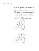
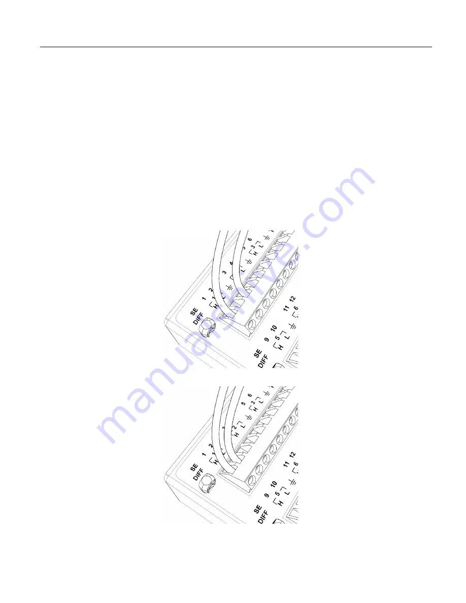
Figure 18. Analog Sensor Wired to Single-Ended Channel #1
Figure 19. Analog Sensor Wired to Differential Channel #1
64
Summary of Contents for CR1000
Page 2: ......
Page 4: ......
Page 6: ......
Page 32: ......
Page 36: ......
Page 38: ......
Page 40: ......
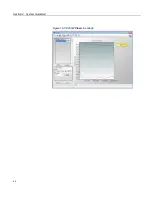
Page 60: ...Section 4 System Quickstart Figure 16 PC200W View Line Graph 60 ...
Page 96: ......
Page 98: ...98 ...
Page 302: ......
Page 453: ...Section 8 Operation Figure 115 Using the Keyboard Display 453 ...
Page 456: ...Section 8 Operation Figure 118 Real Time Custom 456 ...
Page 457: ...Section 8 Operation 8 8 1 3 Final Memory Tables Figure 119 Final Memory Tables 457 ...
Page 458: ...Section 8 Operation 8 8 2 Run Stop Program Figure 120 Run Stop Program 458 ...
Page 460: ...Section 8 Operation Figure 122 File Edit 460 ...
Page 461: ...Section 8 Operation 8 8 4 PCCard Memory Card Display Figure 123 PCCard CF Card Display 461 ...
Page 478: ......
Page 506: ......
Page 536: ......
Page 636: ......
Page 642: ......
Page 644: ......
Page 676: ......
Page 677: ......


