Section 5. System Overview
However, be aware that because a single-ended measurement is referenced to
CR1000 ground, any difference in ground potential between the sensor and the
CR1000 will result in error, as emphasized in the following examples:
•
If the measuring junction of a thermocouple used to measure soil temperature
is not insulated, and the potential of earth ground is greater at the sensor than
at the point where the CR1000 is grounded, a measurement error will result.
For example, if the difference in grounds is 1 mV, with a copper-constantan
thermocouple, the error will be approximately 25 °C.
•
If signal conditioning circuitry, such as might be found in a gas analyzer, and
the CR1000 use a common power supply, differences in current drain and
lead resistance often result in different ground potentials at the two
instruments despite the use of a common ground. A differential measurement
should be made on the analog output from the external signal conditioner to
avoid error.
5.1.2.1.2 Differential Measurements — Overview
Related Topics:
•
Differential Measurements — Overview
(p. 66)
•
Differential Measurements — Details
(p. 308)
Summary
Use a differential configuration when making voltage measurements,
unless constrained to do otherwise.
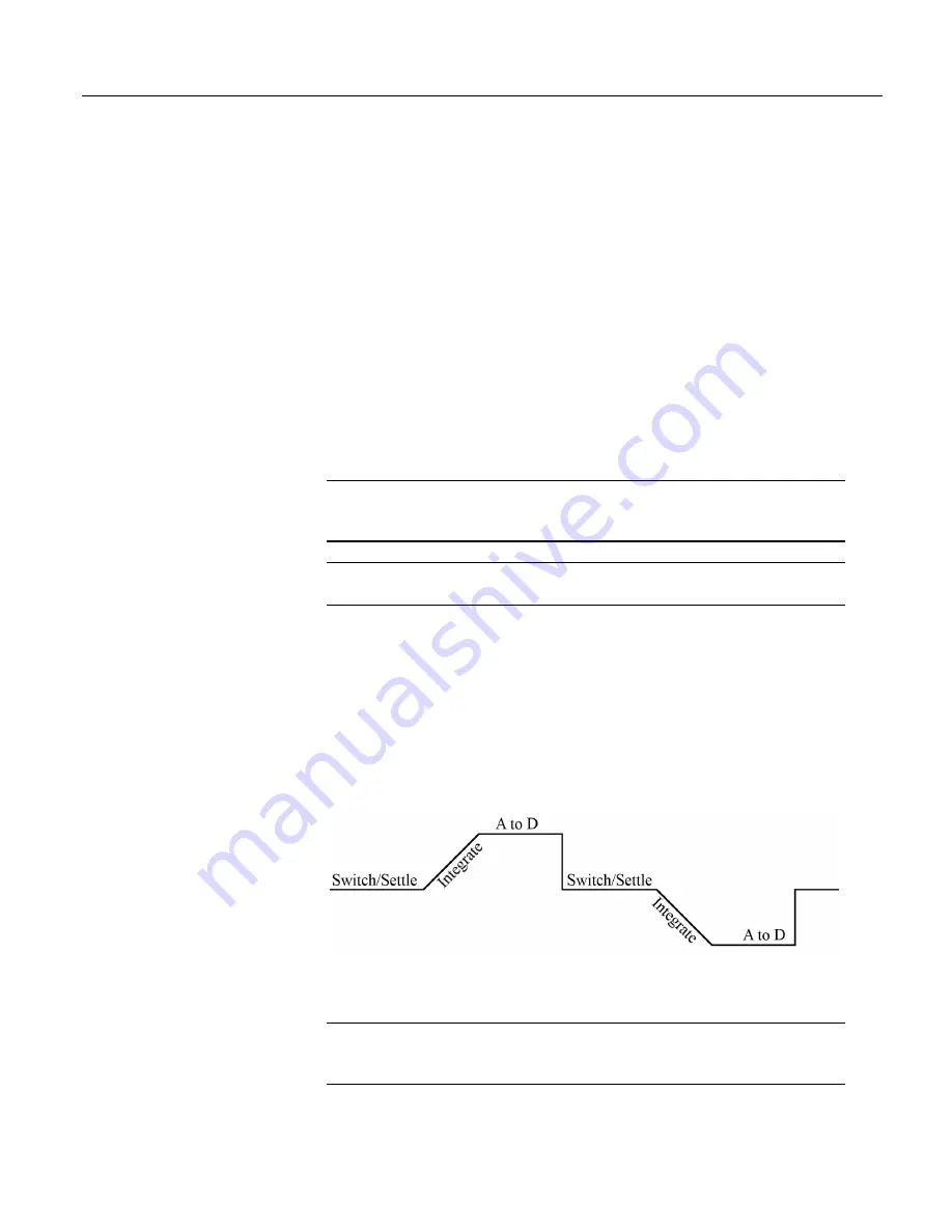
A differential measurement measures the difference in voltage between two input
terminals. Its sequence is illustrated in the figure
Simplified Differential-Voltage
Measurement Sequence
(p. 66),
and is characterized by multiple automatic
measurements, the results of which are averaged automatically before the final
value is reported. For example, the sequence on a differential measurement using
the
VoltDiff()
instruction involves two measurements — first with the high input
referenced to the low, then with the inputs reversed. Reversing the inputs before
the second measurement cancels noise common to both leads as well as small
errors caused by junctions of different metals that are throughout the measurement
electronics.
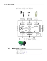
Figure 20. Simplified Differential-Voltage Measurement Sequence
5.1.2.2 Current Measurements — Overview
Related Topics:
•
Current Measurements — Overview
(p. 66)
•
Current Measurements — Details
(p. 337)
66
Summary of Contents for CR1000
Page 2: ......
Page 4: ......
Page 6: ......
Page 32: ......
Page 36: ......
Page 38: ......
Page 40: ......
Page 60: ...Section 4 System Quickstart Figure 16 PC200W View Line Graph 60 ...
Page 96: ......
Page 98: ...98 ...
Page 302: ......
Page 453: ...Section 8 Operation Figure 115 Using the Keyboard Display 453 ...
Page 456: ...Section 8 Operation Figure 118 Real Time Custom 456 ...
Page 457: ...Section 8 Operation 8 8 1 3 Final Memory Tables Figure 119 Final Memory Tables 457 ...
Page 458: ...Section 8 Operation 8 8 2 Run Stop Program Figure 120 Run Stop Program 458 ...
Page 460: ...Section 8 Operation Figure 122 File Edit 460 ...
Page 461: ...Section 8 Operation 8 8 4 PCCard Memory Card Display Figure 123 PCCard CF Card Display 461 ...
Page 478: ......
Page 506: ......
Page 536: ......
Page 636: ......
Page 642: ......
Page 644: ......
Page 676: ......
Page 677: ......


