Section 5. System Overview
always "listening", whereas period averaging may filter the noise by reason of
being "asleep" most of the time. Pulse-count measurements are not appropriate for
sensors that are powered off between scans, whereas period-average
measurements work well since they can be placed in the scan to execute only
when the sensor is powered and transmitting the signal.
Period-average measurements use a high-frequency digital clock to measure time
differences between signal transitions, whereas pulse-count measurements simply
accumulate the number of counts. As a result, period-average measurements offer
much better frequency resolution per measurement interval, as compared to pulse-
count measurements. The frequency resolution of pulse-count measurements can
be improved by extending the measurement interval by increasing the scan
interval and by averaging. For information on frequency resolution, see
Frequency Resolution
(p. 353).
5.1.5 Vibrating-Wire Measurements — Overview
Related Topics:
• Vibrating
-Wire Measurements — Specifications
•
Vibrating-Wire Measurements — Overview
(p. 71)
•
Vibrating-Wire Measurements — Details
(p. 361)
Vibrating-wire sensors impart long term stability to many environmental and
industrial measurement applications. The CR1000 is equipped to measure these
sensors either directly or through interface modules.
A thermistor included in most sensors can be measured to compensate for
temperature errors.
Measuring the resonant frequency by means of period averaging is the classic
technique, but Campbell Scientific has developed static and dynamic spectral-
analysis techniques (
VSPECT
TM
(p. 532)
) that produce superior noise rejection,
higher resolution, diagnostic data, and, in the case of dynamic VSPECT,
measurements up to 333.3 Hz. Dynamic measurements require addition of an
interface module.
SE
terminals are configurable for time-domain vibrating-wire measurement,
which is a technique now superseded in most applications by
VSPECT
(p. 532)
vibrating-wire analysis. See appendix
Vibrating-Wire Input Modules List
(p. 647)
for more information
5.1.6 Reading Smart Sensors — Overview
Related Topics:
•
Reading Smart Sensors — Overview
(p. 71)
•
Reading Smart Sensors — Details
(p. 362)
A smart sensor is equipped with independent measurement circuitry that makes
the basic measurement and sends measurement and measurement related data to
the CR1000. Smart sensors vary widely in output modes. Many have multiple
output options. Output options supported by the CR1000 include
SDI-12
(p. 267),
RS-232
(p. 245),
Modbus
(p. 411),
and
DNP3
(p. 408).
The following smart sensor types can be measured on the indicated terminals:
71
Summary of Contents for CR1000
Page 2: ......
Page 4: ......
Page 6: ......
Page 32: ......
Page 36: ......
Page 38: ......
Page 40: ......
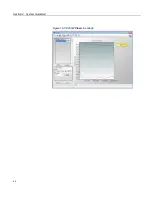
Page 60: ...Section 4 System Quickstart Figure 16 PC200W View Line Graph 60 ...
Page 96: ......
Page 98: ...98 ...
Page 302: ......
Page 453: ...Section 8 Operation Figure 115 Using the Keyboard Display 453 ...
Page 456: ...Section 8 Operation Figure 118 Real Time Custom 456 ...
Page 457: ...Section 8 Operation 8 8 1 3 Final Memory Tables Figure 119 Final Memory Tables 457 ...
Page 458: ...Section 8 Operation 8 8 2 Run Stop Program Figure 120 Run Stop Program 458 ...
Page 460: ...Section 8 Operation Figure 122 File Edit 460 ...
Page 461: ...Section 8 Operation 8 8 4 PCCard Memory Card Display Figure 123 PCCard CF Card Display 461 ...
Page 478: ......
Page 506: ......
Page 536: ......
Page 636: ......
Page 642: ......
Page 644: ......
Page 676: ......
Page 677: ......


