Section 5. System Overview
•
SDI-12 devices:
C
•
Synchronous Devices for Measurement (SDM):
C
•
Smart sensors:
C
terminals,
RS-232
port, and
CS I/O
port with the
appropriate interface.
•
Modbus or DNP3 network:
RS-232
port and
CS I/O
port with the appropriate
interface
•
Other serial I/O devices:
C
terminals,
RS-232
port, and
CS I/O
port with the
appropriate interface
5.1.6.1 SDI-12 Sensor Support — Overview
Related Topics:
•
SDI-12 Sensor Support — Overview
(p. 72)
•
SDI-12 Sensor Support — Details
(p. 363)
•
Serial I/O: SDI-12 Sensor Support — Programming Resource
(p. 267)
•
SDI-12 Sensor Support — Instructions
(p. 555)
SDI-12 is a smart-sensor protocol that uses one SDI-12 port and is powered by 12
Vdc. It is fully supported by the CR1000 datalogger. Refer to the chart
CR1000
Terminal Definitions
(p. 76),
which indicates
C
terminals that can be configured for
SDI-12 input. For more information about SDI-12 support, see section
Serial I/O:
SDI-12 Sensor Support — Details
(p. 267).
5.1.6.2 RS-232 — Overview
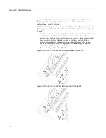
The CR1000 has 6 ports available for RS-232 input as shown in figure
Terminals
Configurable for RS-232 Input
(p. 73).
Note
With the correct adapter, the
CS I/O
port can often be used as an RS-232
I/O port.
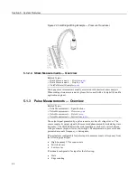
As indicated in figure
Use of RS-232 and Digital I/O when Reading RS-232
Devices
(p. 73),
RS-232 sensors can often be connected to
C
terminal pairs
configured for serial I/O, to the
RS-232
port, or to the
CS I/O
port with the proper
adapter. Ports can be set up for baud rate, parity, stop-bit, and so forth as
described in
CRBasic Editor Help
.
72
Summary of Contents for CR1000
Page 2: ......
Page 4: ......
Page 6: ......
Page 32: ......
Page 36: ......
Page 38: ......
Page 40: ......
Page 60: ...Section 4 System Quickstart Figure 16 PC200W View Line Graph 60 ...
Page 96: ......
Page 98: ...98 ...
Page 302: ......
Page 453: ...Section 8 Operation Figure 115 Using the Keyboard Display 453 ...
Page 456: ...Section 8 Operation Figure 118 Real Time Custom 456 ...
Page 457: ...Section 8 Operation 8 8 1 3 Final Memory Tables Figure 119 Final Memory Tables 457 ...
Page 458: ...Section 8 Operation 8 8 2 Run Stop Program Figure 120 Run Stop Program 458 ...
Page 460: ...Section 8 Operation Figure 122 File Edit 460 ...
Page 461: ...Section 8 Operation 8 8 4 PCCard Memory Card Display Figure 123 PCCard CF Card Display 461 ...
Page 478: ......
Page 506: ......
Page 536: ......
Page 636: ......
Page 642: ......
Page 644: ......
Page 676: ......
Page 677: ......


