CR10X User Guide
7-8
Connections
Anemometer
+12V Supply
Ground and Signal Reference
Pulse Out
CR10
+12V
G
P1
Figure 7-5 Wiring Diagram for Anemometer
Program
01:Pulse (P3)
01:
1
Rep
02:
1
Pulse Input Chan
03:
20
High frequency; Output Hz.
04:
10
Loc [:WS MS
-1
]
05:
.09792
Mult
06:
0.2
Offset
7.8 Tipping Bucket Raingauge with Long Leads
A tipping bucket raingauge is monitored with the Pulse Count instruction con-
figured for Switch Closure. Counts from long intervals are used, as the final
output desired is total rainfall (obtained with Instruction 72, Totalize). If counts
from long intervals were discarded, less rainfall would be recorded than was
actually measured by the gauge (assuming there were counts in the long inter-
vals). Output is desired in millimetres of precipitation. The gauge is calibrated for
a 0.2mm tip, so a multiplier of 0.2 is used.
In a long cable there is appreciable capacitance between the conductors. The
capacitance is discharged across the switch when it closes. In addition to short-
ening switch life, a transient may be induced in other wires packaged with the rain
gauge leads each time the switch closes. The 100 ohm resistor protects the switch
from arcing and the associated transient from occurring, and should be included
whenever leads longer than 30m are used.
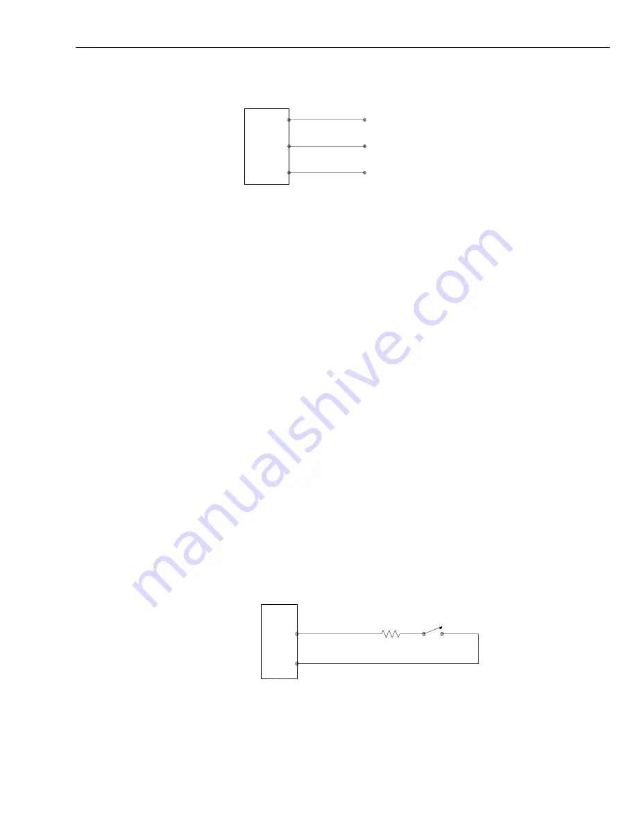
Connections
P1
CR10
100
Raingauge
Ω
G
30m lead length
Figure 7-6 Wiring Diagram for Raingauge with Long Leads
CR10X
CR10X


