CR10X Reference Manual
13-20
before the integration portion of the measurement starts and is grounded as soon
as the integration is completed. Figure 13-16 shows the excitation and
measurement sequence for Instruction 6, a 4-wire full bridge. Excitation is applied
separately for each phase of a bridge measurement. For example, in Instruction 6,
as shown in Figure 13-16, excitation is switched on for the four integration
periods and switched off between integrations.
The measurement sequence for Instruction 8 consists of applying a single excita-
tion voltage, delaying a specified time, and making a differential voltage
measurement. If a delay of 0 is specified, the inputs for the differential meas-
urement are not switched for a second integration as is normally the case (see
Section 13.2). The result stored is the voltage measured. The resolution and
common mode rejection of Instruction 8 are not as good as the ratiometric bridge
measurement instructions. It does, however, provide a very rapid means of
making bridge measurements as well as supplying excitation to circuitry requiring
differential measurements. This instruction does not reverse excitation. A 1 before
the excitation channel number (i.e. 1x, where x is the initial excitation channel
number) causes the channel to be incremented with each repetition.
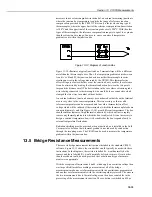
Figure 13-15 Circuits Used with Instructions 4 to 9


