SECTION 5. TELECOMMUNICATIONS
K
CURRENT INFORMATION
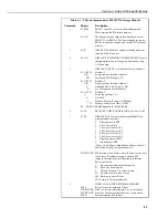
- In response to the K command, the CR10X sends
datalogger time, user flag status, the data at the input locations requested in the J
command, and Final Storage Data if requested by the J command. Used in the
Monitor Mode and with Heads Up Display. See Appendix C.
[Password]
L
UNLOCKS SECURITY
(if enabled) to the level determined by the password
entered (See *C Mode, Section 1). CR10X sends security level (0-3) and
checksum: Sxx Cxxxx
[X]
M
CONNECT TO STORAGE MODULE
with address ‘X’ and enter the Storage
Module’s Telecommunications Mode (see Storage Module manual). The
SM192/716 Storage Module can also be accessed with the *9 Mode commands
while in the Remote Keyboard State (see Section 4 and the Storage Module
manual).
1N
CONNECT PHONE MODEM TO RF
modem at phone to RF base station.
19287P
DISPLAY/SET INTERNAL CORRECTION FACTORS
- This command is used to
display and/or set the internal correction factors that improve the accuracy of the
internal clock used for period measurements (for example with Instructions 27 and
28). These coefficients are set during manufacture, and should not normally be
altered. The command must be entered as 19287P (entering ‘P’ alone will produce an
error).
Entering
19287P
will display two coefficient numbers (e.g. 0.8944 and 8133). If the two
numbers are -99999, and you intend to use Instruction 27 or 28, the datalogger will
need to be re-calibrated by Campbell Scientific. As a short-term measure, to allow
periodic measurements to be made, these values can be set to their default setting by
using the
19287:800P
command as shown below.
Entering
19287:800P
will return the datalogger to its default coefficients. These
assume that the clock is running at its ideal design frequency, and therefore using
these settings may result in additional small errors on measurements made with
Instructions 27 and 28. These additional errors could be up to 0.01%
S
RETURN MEMORY ALLOCATION REGISTERS
- Returns Mode A Memory
Allocation registers (first group of 01: to 06) and Mode B Status/On-board Firmware
registers (second group of 01: to 11).
T
SDM-SIO4 TALK THROUGH COMMAND
Address: Port T
Address = 0..15
Port = 0..4
5-4


