background image

CR200 Overview 

Address 1

.  When prompted with the option to 

Test Communications

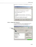
 click 

the 

Finish

 button. 

To change a setting in the datalogger setup, select that datalogger from the 
main window, and click the 

Edit

 button.  If a datalogger was not added with 

the Wizard, click the 

Add

 button to invoke the Wizard. 

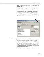
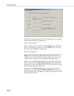
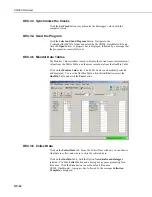
After exiting the EZSetup wizard, the 

Setup/Connect

 window appears, as 

shown below.  The Current Datalogger Profile, Datalogger Clock, and 
Datalogger Program features of PC200W are integrated into this window.  
Tabs to the right are used to select the 

Monitor Values

 and 

Collect Data


windows.  Buttons to the right of the tabs are used to run the 

Split

View

, and 

Short Cut

 applications.  


Short Cut


OV4.3.1  Creating a CR200 Program using Short Cut 

Objective: Every 10 seconds measure air temperature (°C) with a 109 
Temperature Probe, and rainfall (mm) with a TE525WS rain gage. Every 1-
minute store average temperature, total rainfall, and minimum battery voltage.  

Even if the 109 Temperature Probe and TE525WS Rain Gage sensors are not 
available, the programming  example can still be followed.  Without a 109 
probe connected the measurement result will be NAN;  without a TE525WS 
connected the measurement result will be 0. 

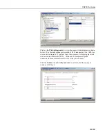
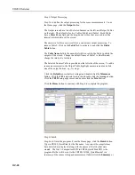
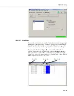
Click on the 

Short Cut

 button to display the 

Home

 screen, as shown below. 

OV-17 

Summary of Contents for CR200

Page 1: ...CR200 Series Datalogger Overview Revision 3 07 C o p y r i g h t 2 0 0 0 2 0 0 6 C a m p b e l l S c i e n t i f i c I n c...

Page 2: ......

Page 3: ...munication with the CR200 OV 11 OV2 5 Serial ASCII Communication with the CR200 OV 11 OV3 CR200 Setup using the Device Configurator Utility OV 11 OV3 1 Power and Communication Connections to the CR200...

Page 4: ...e FCC Approved Antennas OV 8 OV1 5 Example COAX RPSMA L Cable for Yagi or Omni Colinear OV 9 OV1 6 Antenna Surge Protector OV 9 OV2 1 512K on the datalogger label indicates the larger memory OV 10 OV3...

Page 5: ...Canada CR205 Retired 915 MHz U S Canada CR211 922 MHz Australia Israel CR210 Retired 922 MHz Australia Israel CR216 2 4 GHz Worldwide CR215 Retired 2 4 GHz Worldwide The CR295 includes an additional...

Page 6: ...nts Battery SIGNAL AND SHIELD GROUNDS SWITCHED BATTERY SWBatt CHARGE INPUT RS 232 SWITCHED VOLTAGE EXCITATION ExDelSE CONTROL I O SDI12 PortGet PortSet SDI12Recorder 512K The 512K label indicates the...

Page 7: ...digital control SDI 12 communication OV1 1 8 Power In The Batt and Batt terminals are for connecting power from an external battery to the CR200 The CR200 will operate on 7 to 16 VDC These are the on...

Page 8: ...trically isolated Connection to an AC powered computer may cause ground loops leading to measurement problems Maximum input 25 V Maximum Output 13 V Typical Ou TABLE OV1 1 Comp ABR Abbreviation for th...

Page 9: ...ong 14204 0 dBd ANTENNA 900 MHZ OMNI WAVE WHIP RPSMA RT ANGLE ASTRON 6 75 inches long 14221 3 dBd ANTENNA 900 MHZ OMNI COLLINEAR ANTENEX FG9023 24 inches tall W FM2 MOUNTS fits 1 in to 2 in O D mast r...

Page 10: ...he antenna characteristics Thus a low power transmitter that complies with the technical standards in Part 15 with a particular antenna attached can exceed the Part 15 standards if a different antenna...

Page 11: ...CR200 Overview ITEM 14201 900 MHZ YAGI 9 dBd w MOUNTS ITEM 14205 900 MHz YAGI 6 dBd w MOUNTS ITEM 14221 900 MHZ OMNI COLLINEAR 3 dBd w MOUNTS OV 7...

Page 12: ...Overview ITEM 15970 900 MHZ Indoor OMNI 1 dBd Window Wall Mounted ITEM 16005 2 4 GHz OMNI HALF WAVE WHIP 0 dBd ITEM 16755 2 4 GHz ENCLOSED YAGI 13 dBd w MOUNTS FIGURE OV1 4 Some FCC Approved Antennas...

Page 13: ...The CR200 has 2K SRAM for communication buffers calculations and variables and 60K Flash EEPROM for the operating system and user program Dataloggers originally had a 128K Serial Flash EEPROM for dat...

Page 14: ...er datalogger Data are retrieved from the master rather than the CR20X OV2 3 Data Tables The CR200 can store individual measurements or it may use its processing capabilities to calculate averages max...

Page 15: ...ips with the LoggerNet PC400 and PC200W software products and is also available no charge from the Campbell Scientific website The Device Configuration Utility DevConfig sets up dataloggers and periph...

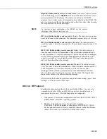
Page 16: ...default setting To change settings the Device Configuration Utility DevConfig is used as described below To set the PakBus address the CR200 must be powered up and connected to the computer as descri...

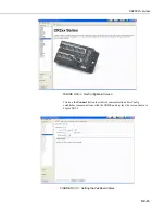
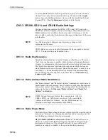
Page 17: ...2 DevConfig Main Screen Click on the Connect button to establish communications DevConfig establishes communications with the CR200 and displays the screen shown in Figure OV3 3 FIGURE OV3 3 Setting...

Page 18: ...e in which the hops are made Radios must be set to the same Radio Hop Sequence in order to hear each other i e for the listening radio to synchronize with the transmitting radio and hop to the same fr...

Page 19: ...ations with SendGetData and other radios in the system are using the 1 second standby mode The long header insures other radios in the network hear the message RF8S_LH Radio standby receive current 0...

Page 20: ...or creating CR200 programs and tools for configuring trouble shooting and managing datalogger networks OV4 1 1 Options for Creating CR200 Programs 1 Short Cut is a program generator that creates a dat...

Page 21: ...elect the Monitor Values and Collect Data windows Buttons to the right of the tabs are used to run the Split View and Short Cut applications Short Cut OV4 3 1 Creating a CR200 Program using Short Cut...

Page 22: ...t is divided into two sections the Available sensors tree and the Selected sensors table as shown below The sensors you want to measure are chosen from the Available sensors tree Double click on the T...

Page 23: ...TE525 rain gauge to the CR200 as shown on the diagram If you don t have these sensors a simple toggle switch can be used to simulate the TE525 Without a 109 temperature probe connected the measurement...

Page 24: ...interval to 1 minute The Selected Sensors Table is provided on the left side of the screen To add a sensor measurement to the Output Table highlight a measurement and click one of the output buttons...

Page 25: ...ton and close Short Cut OV4 3 2 Configuring the Setup Tab From the Setup Connect screen click on the Connect button to establish communications with the CR200 When communications have been established...

Page 26: ...es from the Public Table and the most recent data from the OneMin Table Click on the Monitor Values tab The Public Table is automatically selected and displayed To view the OneMin Table click the Add...

Page 27: ...toolbar icon for a few seconds a brief description of that icon s function will appear To open a data file click the Open file icon and double click on the file CR200_OneMin dat in the PC200W folder C...

Page 28: ...eated the program The program file listed below is the Short Cut file 200_QuickStart CR1 from the tutorial after being imported into the CRBasic editor See Section 4 for information on the CRBasic pro...

Page 29: ...ry Voltage measurement Batt_Volt Battery Batt_Volt 109 Temperature Probe measurement T109_C Therm109 T109_C 1 1 1 1 0 0 0 TE525 TE525WS Rain Gauge measurement Rain_mm PulseCount Rain_mm P_SW 2 0 0 254...

Page 30: ...radios 0 6 miles 1 km with 0 dBd wave antenna line of sight and 2 4 GHz radio up to 10 miles with higher gain antenna line of sight RF4XX used as a base station radio AVAILABLE RADIO TRANSMISSION MOD...

Page 31: ...This is a blank page...

Page 32: ...campbellsci com br suporte campbellsci com br Campbell Scientific Canada Corp CSC 11564 149th Street NW Edmonton Alberta T5M 1W7 CANADA www campbellsci ca dataloggers campbellsci ca Campbell Scientif...

Reviews: