CR200 Overview
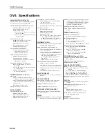
OV5. Specifications
ANALOG INPUTS; DIGITAL I/O
Ch
a
nnel
s
S
E1 to
S
E5 c
a
n be individu
a
lly configured
for
s
ingle-ended me
as
urement or digit
a
l I/O.
S
INGLE-ENDED MEA
S
UREMENT (
S
E1 TO
S
E5):
An
a
log Input R
a
nge: 0
≤
V
<
2.5 Vdc
Me
as
urement Re
s
olution: 0.6 mV
Me
as
urement Accur
a
cy
Typic
a
l: ±(0.25% of re
a
ding + 1.2 mV off
s
et)
over
-40°
to
+50°C
Wor
s
t-c
as
e: ±(1% of re
a
ding + 2.4 mV off
s
et)
over -40° to 50°C
DIGITAL I/O (
S
E1 TO
S
E5):
Input/Output
High
S
t
a
te: 2.1 to
3
.
3
Vdc
Input/Output
Low
S
t
a
te: <0.
9
Vdc
Output
High
S
t
a
te:
3
.
3
V (no lo
a
d)
Drive Current: 220 µA @ 2.7 Vdc
M
a
ximum Input Volt
a
ge: 4 Vdc
HALF BRIDGE MEA
S
UREMENT
S
:
Accur
a
cy: Rel
a
tive to the excit
a
tion.
U
s
ing +2.5 Vdc excit
a
tion, i
s
±(0.06% of re
a
ding + 2.4 mV)
PERIOD AVERAGING (
S
E1 TO
S
E4):
M
a
ximum Input Volt
a
ge: 4 Vdc
Frequency
R
a
nge: 0 to 150 kHz
Volt
a
ge Thre
s
hold: count
s
cycle
s
on tr
a
n
s
ition
from
<0.
9
Vdc to >2.1 Vdc
EXCITATION CHANNEL
S
(EX1 AND EX2):
R
a
nge: Progr
a
mm
a
ble 0, 2.5, 5 Vdc, or
off
(flo
a
ting)
Accur
a
cy: ±25 mV on +2.5 Vdc r
a
nge, ±125 mV
on +5.0 Vdc r
a
nge
M
a
ximum Current: 25 mA on +2.5 Vdc r
a
nge,
10 mA on +5.0 Vdc r
a
nge
CONTROL PORTS (C1 AND C2)
DIGITAL I/O:
Volt
a
ge Level When Configured
as
Input:
<0.
9
Vdc (low
s
t
a
te) to >2.7 Vdc (high
s
t
a
te)
Volt
a
ge Level When Configured
as
Output:
0
V
(low
s
t
a
te), 5 Vdc (high
s
t
a
te) (no lo
a
d)
Logic
Level:
TTL
Drive Current: 1.5 mA @ 4.5 V
S
DI-12:
S
DI-12
s
en
s
or
s
connect to C1
PULSE COUNTERS
S
WITCH CLO
S
URE (P_
S
W):
M
a
ximum Count R
a
te: 100 Hz
Minimum
S
witch Open Time: 5 m
s
Minimum
S
witch Clo
s
ed Time: 5 m
s
M
a
ximum Bounce Time: 4 m
s
PUL
S
E COUNT (P_
S
W, C1, AND C2):
Volt
a
ge Thre
s
hold: count on tr
a
n
s
ition from
<0.
9
V to >2.7 Vdc
M
a
ximum Input Frequency: 1 kHz
M
a
x Input Volt
a
ge: C1 & C2 (6.5 V), P_
S
W (4 Vdc)
LOW LEVEL AC (P_LL):
Volt
a
ge Thre
s
hold: <0.5 to >2 V
Minimum Input: 20 mV RM
S
M
a
ximum Frequency: 1 kHz
M
a
ximum Input: ±20 V
Note: P_LL, C1, & C2 can be used for switch
closure using the battery voltage and a
20 kOhm pull-up resistor. If the dc offset is
>0.5 V, then AC coupling is required.
COMMUNICATIONS
S
ERIAL INTERFACE: Fem
a
le R
S
-2
3
2
9
-pin interf
a
ce
for logger-to-PC communic
a
tion
s
ON-BOARD
S
PREAD
S
PECTRUM RADIO:
Frequency:
9
15 MHz (CR206),
9
22 MHz (CR211),
or 2.4 GHz (CR216)
Tr
a
n
s
mi
ss
ion R
a
nge: 1 mile with 0 dBd ¼ w
a
ve
a
ntenn
a
(line-of-
s
ight)
a
nd
9
00 MHz r
a
dio
s
;
0.6
mile
s
(1 km) with 0 dBd ½ w
a
ve
a
ntenn
a
(line-of-
s
ight)
a
nd 2.4 GHz r
a
dio;
up to 10 mile
s
with higher g
a
in
a
ntenn
a
(line-of-
s
ight)
RF4XX
u
s
ed
as
a
b
as
e
s
t
a
tion r
a
dio
AVAILABLE RADIO TRAN
S
MI
SS
ION MODE
S
:
Alw
a
y
s
on, progr
a
m controlled
Cycle Time: 1 or
8
s
cycle
s
; on for 100 m
s
every
period;
check
s
for incoming communic
a
tion
S
cheduled Tr
a
n
s
mi
ss
ion Time: off until tr
a
n
s
mi
s
-
s
ion time
P
AK
B
U
S
® p
a
cket
s
witching network protocol
CLOCK ACCURACY
8
.2 minute
s
/month @ -40° to +50°C; 1 minute/month
@
+25°C
CPU AND STORAGE
FINAL
S
TORAGE: 512 kbyte Fl
as
h, d
a
t
a
form
a
t
i
s
4 byte
s
per d
a
t
a
point (t
a
ble-b
as
ed)
PROGRAM
S
TORAGE: 6.5 kbyte Fl
as
h
FA
S
TE
S
T
S
CAN RATE: once per
s
econd
SWITCHED BATTERY (SW BATTERY)
S
witched under progr
a
m control;
3
00 mA minimum
current
a
v
a
il
a
ble
POWER
BATTERY VOLTAGE RANGE: 7 to 16 Vdc (c
a
n progr
a
m
d
a
t
a
logger to me
as
ure intern
a
l b
a
ttery volt
a
ge)
BATTERY: 12 Vdc
s
e
a
led rech
a
rge
a
ble with on-bo
a
rd
ch
a
rging circuit. Alk
a
line cell
s
, lithium, or other
non-rech
a
rge
a
ble b
a
ttery type
s
m
a
y be connected
if the ch
a
rging circuit i
s
not u
s
ed (i.e. nothing
connected to ch
a
rging termin
a
l
s
).
CHARGER INPUT VOLTAGE: 16 to 22 Vdc
S
HELF LIFE OF CLOCK’
S
BACKUP BATTERY:
5
ye
a
r
s
CURRENT DRAIN (@12 V)
QUIE
S
CENT CURRENT DRAIN:
No
R
a
dio or R
a
dio Powered Off:
~
0.2 mA
ACTIVE CURRENT DRAIN:
No
r
a
dio
~
3
mA
R
a
dio receive
~
20 mA (CR206, CR211),
~
3
6 mA (CR216)
R
a
dio tr
a
n
s
mit
~
75 mA (CR206, CR211, CR216)
AVERAGE CONTINUOU
S
CURRENT DRAIN:
R
a
dio
a
lw
a
y
s
on
~
20 mA (CR206, CR211),
~
3
6 mA (CR216)
R
a
dio in 1
s
duty cycle
~
2.2 mA (CR206,
CR211),
~
4 mA (CR216)
R
a
dio in
8
s
duty cycle
~
0.45 mA (CR206,
CR211),
~
0.
8
mA (CR216)
CE COMPLIANCE (as of 03/02)
CE COMPLIANT DATALOGGER
S
: CR200, CR206,
CR211,
CR216
S
TANDARD(
S
) TO WHICH CONFORMITY I
S
DECLARED: IEC61
3
26:2002
EMI AND ESD PROTECTION
IMMUNITY: Meet
s
or exceed
s
following
s
t
a
nd
a
rd
s
:
E
S
D: per IEC 1000-4-2; ±
8
kV
a
ir, ±4 kV cont
a
ct
di
s
ch
a
rge
RF: per IEC 1000-4-
3
;
3
V/m,
8
0-1000 MHz
EFT: per IEC 1000-4-4; 1 kV power, 500 V I/O
S
urge: per IEC 1000-4-5; 1 kV power
a
nd I/O
Conducted:
per
IEC 1000-4-6;
3
V 150 kHz-
8
0 MHz
Emi
ss
ion
s
a
nd immunity perform
a
nce criteri
a
a
v
a
il
a
ble
on reque
s
t.
PHYSICAL
CA
S
E DE
S
CRIPTION: Aluminum with
s
pring-lo
a
ded
termin
a
l
s
DIMEN
S
ION
S
(including termin
a
l
s
): 5.5” x
3
” x 2”
(14.0 x 17.6 x 5.1 cm)
WEIGHT:
CR200 or CR2
9
5:
8
.5 oz (242 g)
CR206, CR211, or CR216:
9
.5 oz (271 g)
CU
S
TOM CA
S
E:
a
v
a
il
a
ble for OEM
a
pplic
a
tion
s
;
cont
a
ct C
a
mpbell
S
cientific
WARRANTY
One ye
a
r covering p
a
rt
s
a
nd l
a
bor.
OV-26
Summary of Contents for CR200
Page 2: ......
Page 31: ...This is a blank page...


