Section 2. Quickstart Tutorial
14
2.
A new window will appear showing the option to create a new program
or open an existing program. Select New Program.
3.
A drop-down list will appear showing different dataloggers. Select the
CR200(X) and click OK.
4.
The program will now ask for the scan interval. Set the interval to 10
seconds and click OK.
5.
A second prompt will ask for a choice of "Sensor Support." Select
"Campbell Scientific, Inc."
6.
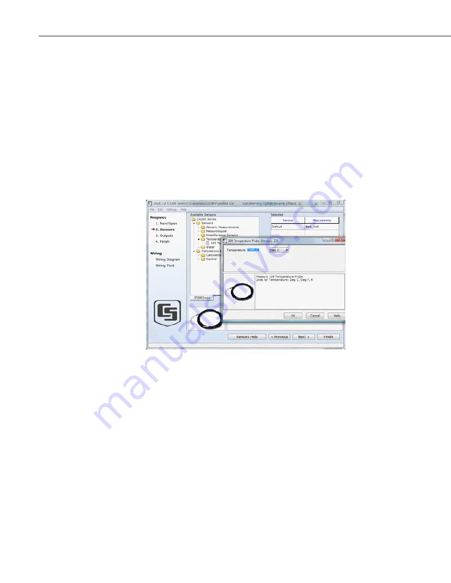
Under Available Sensors, expand the "Sensors" folder by clicking on
the "+" symbol. This shows several sub-folders. Expand the
"Temperature" folder to view the available sensors.
Figure 12: Short Cut Temperature Sensor Folder
2.2.3.1.3
Procedure (Short Cut Steps 7–9)
1.
Double-click the 109 Temperature Probe sensor to add it to the
Selected category. Alternatively, highlight the Wiring Panel
Temperature sensor by clicking on it once, and then click on the arrow
between Available Sensors and Selected to add it to the Selected
sensors.
2.
Click
OK
on the next screen to accept T109_C for the measurement
label, the DegC for the units.
3.
Double click on the
Meteorological
application group. Double click
on Precipitation, and double click on the
TE525 / TE525WS
sensor to
add it to the selected sensors table. Click OK to accept Rain_mm for
the measurement label, and mm for the units.
Summary of Contents for CR200
Page 32: ...Section 2 Quickstart Tutorial 22 ...
Page 45: ...Section 3 Overview 35 3 3 Specifications ...
Page 46: ...Section 3 Overview 36 ...
Page 58: ...Section 4 Sensor Support 48 ...
Page 62: ...Section 5 Measurement and Control Peripherals 52 ...
Page 78: ...Section 8 CR200 X Configuration 68 ...
Page 102: ...Section 9 Programming 92 ...
Page 138: ...Section 11 Programming Resource Library 128 ...
Page 156: ...Section 16 Support Software 146 ...
Page 160: ...Section 17 Care and Maintenance 150 ...
Page 167: ...Section 18 Troubleshooting 157 18 3 3 2 Charging Circuit Test Solar Panel ...
Page 168: ...Section 18 Troubleshooting 158 18 3 3 3 Charging Circuit Test Transformer ...
Page 169: ...Section 18 Troubleshooting 159 18 3 3 4 Adjusting Charging Circuit Voltage ...
Page 170: ...Section 18 Troubleshooting 160 ...
Page 184: ...Appendix A Glossary 14 ...
Page 190: ...Appendix B Status Table and Settings 20 ...
Page 192: ...Appendix C Serial Port Pin Outs 22 ...
Page 211: ......


