Section 8. Operation
433
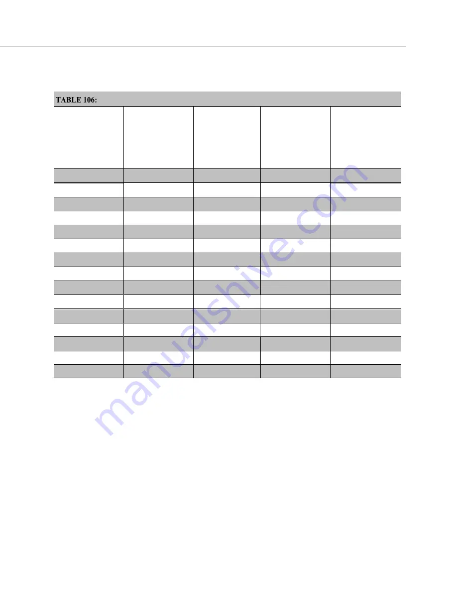
TABLE: Offset Voltage Compensation Options
(p. 399)
lists some of the tools
available to minimize the effects of offset voltages.
Offset Voltage Compensation Options
CRBasic
Measurement
Instruction
Input Reversal
(
RevDiff
=
True
)
Excitation
Reversal
(
RevEx
=
True
)
Measure
Offset During
Measurement
(
MeasOff
=
True
)
Measure Offset
During
Background
Calibration
(
RevDiff
=
False
)
(
RevEx
=
False
)
(
MeasOff
=
False
)
AM25T()
BrHalf()
BrHalf3W()
BrHalf4W()
BrFull()
BrFull6W()
Resistance()
TCDiff()
TCSe()
Therm107()
Therm108()
Therm109()
Thermistor()
VoltDiff()
VoltSe()
Input and Excitation Reversal
Reversing inputs (differential measurements) or reversing polarity of excitation
voltage (bridge measurements) cancels stray voltage offsets. For example, if 3
µ
V offset exists in the measurement circuitry, a 5 mV signal is measured as 5.003
mV. When the input or excitation is reversed, the second sub-measurement is
–4.997 mV. Subtracting the second sub-measurement from the first and then
dividing by 2 cancels the offset:
5.003 mV – (–4.997 mV) = 10.000 mV
10.000 mV / 2 = 5.000 mV
When the CR6 reverses differential inputs or excitation polarity, it delays the
same settling time after the reversal as it does before the first sub-measurement.
So, there are two delays per measurement when either
RevDiff
or
RevEx
is used.
If both
RevDiff
and
RevEx
are
True
, four sub-measurements are performed;
positive and negative excitations with the inputs one way and positive and
Summary of Contents for CR6 Series
Page 2: ......
Page 4: ......
Page 6: ......
Page 32: ......
Page 36: ......
Page 38: ......
Page 76: ...Section 5 Overview 76 FIGURE 20 Half Bridge Wiring Example Wind Vane Potentiometer ...
Page 80: ...Section 5 Overview 80 FIGURE 23 Pulse Input Wiring Example Anemometer ...
Page 136: ......
Page 454: ...Section 8 Operation 454 FIGURE 104 Narrow Sweep High Noise ...
Page 459: ...Section 8 Operation 459 FIGURE 106 Vibrating Wire Sensor Calibration Report ...
Page 535: ...Section 8 Operation 535 8 11 2 Data Display FIGURE 121 CR1000KD Displaying Data ...
Page 537: ...Section 8 Operation 537 FIGURE 123 CR1000KD Real Time Custom ...
Page 538: ...Section 8 Operation 538 8 11 2 3 Final Storage Data FIGURE 124 CR1000KD Final Storage Data ...
Page 539: ...Section 8 Operation 539 8 11 3 Run Stop Program FIGURE 125 CR1000KD Run Stop Program ...
Page 541: ...Section 8 Operation 541 FIGURE 127 CR1000KD File Edit ...
Page 546: ......
Page 552: ......
Page 610: ...Section 11 Glossary 610 FIGURE 137 Relationships of Accuracy Precision and Resolution ...
Page 612: ......
Page 648: ......
Page 650: ......
Page 688: ......
Page 689: ......


