Section 8. Operation
445
o
Timeout expires
o
The signal frequency is too fast (> 3 KHz). When a
C
terminal
experiences a too fast frequency, the CR6 operating system disables
the interrupt that is capturing the precise time until the next scan is
serviced. This is done so that the CR6 processor does not get
occupied by excessive interrupts. A small RC filter retrofitted to
the sensor switch should fix the problem.
8.1.3.8 Pulse Measurement Tips
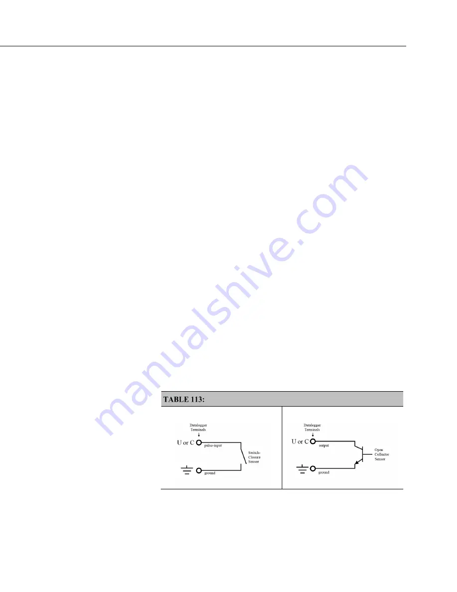
Basic connection of pulse-output sensors is illustrated in table
Switch Closures
and Open Collectors
(p. 445).
The
PulseCount()
instruction, whether measuring pulse inputs on
U
or
C
terminals, uses dedicated 24-bit counters to accumulate all counts over the
programmed scan interval. The resolution of pulse counters is one count or 1 Hz.
Counters are read at the beginning of each scan and then cleared. Counters will
overflow if accumulated counts exceed 16,777,216, resulting in erroneous
measurements.
•
Counts are the preferred
PulseCount()
output option when measuring
the number of tips from a tipping-bucket rain gage or the number of
times a door opens. Many pulse-output sensors, such as anemometers
and flow meters, are calibrated in terms of frequency (
Hz
(p. 586)
) so are
usually measured using the
PulseCount()
frequency-output option.
•
Accuracy: see
Pulse Counting Function — Specifications
(p. 110)
•
Use the
LLAC4
(p. 652)
module to convert non-TTL-level signals,
including low-level ac signals, to TTL levels for input into
C
terminals.
•
When a
U
or
C
terminal is configured for switch closure or
high-frequency pulse, it will be internally configured as a pull-up to
logic
high
(p. 590).
Switch Closures and Open Collectors
Switch Closure on
U
or
C
Terminal
Open Collector on
U
or
C
Terminal
Summary of Contents for CR6 Series
Page 2: ......
Page 4: ......
Page 6: ......
Page 32: ......
Page 36: ......
Page 38: ......
Page 76: ...Section 5 Overview 76 FIGURE 20 Half Bridge Wiring Example Wind Vane Potentiometer ...
Page 80: ...Section 5 Overview 80 FIGURE 23 Pulse Input Wiring Example Anemometer ...
Page 136: ......
Page 454: ...Section 8 Operation 454 FIGURE 104 Narrow Sweep High Noise ...
Page 459: ...Section 8 Operation 459 FIGURE 106 Vibrating Wire Sensor Calibration Report ...
Page 535: ...Section 8 Operation 535 8 11 2 Data Display FIGURE 121 CR1000KD Displaying Data ...
Page 537: ...Section 8 Operation 537 FIGURE 123 CR1000KD Real Time Custom ...
Page 538: ...Section 8 Operation 538 8 11 2 3 Final Storage Data FIGURE 124 CR1000KD Final Storage Data ...
Page 539: ...Section 8 Operation 539 8 11 3 Run Stop Program FIGURE 125 CR1000KD Run Stop Program ...
Page 541: ...Section 8 Operation 541 FIGURE 127 CR1000KD File Edit ...
Page 546: ......
Page 552: ......
Page 610: ...Section 11 Glossary 610 FIGURE 137 Relationships of Accuracy Precision and Resolution ...
Page 612: ......
Page 648: ......
Page 650: ......
Page 688: ......
Page 689: ......


