Section 4. Quickstart
48
4.6.4.1 Procedure: (Short Cut Steps 1 to 5)
1. Click on the
Short Cut
icon in the upper-right corner of the
PC200W
window.
The icon resembles a clock face.
2. The
Short Cut
window is shown. Click
New Program
.
3. In the
Datalogger Model
drop-down list, select
CR6
.
4. In the
Scan Interval
box, enter
1
and select
Seconds
in the drop-down list
box. Click
Next
.
Note
The first time
Short Cut
is run, a prompt will appear asking for a
choice of ac noise rejection. Select
60 Hz
for the United States and other
areas using 60 Hz ac voltage. Select
50 Hz
for most of Europe and other
areas that operate at 50 Hz. A second prompt lists sensor support options.
Campbell Scientific, Inc. (US)
is probably the best fit if you are outside
Europe.
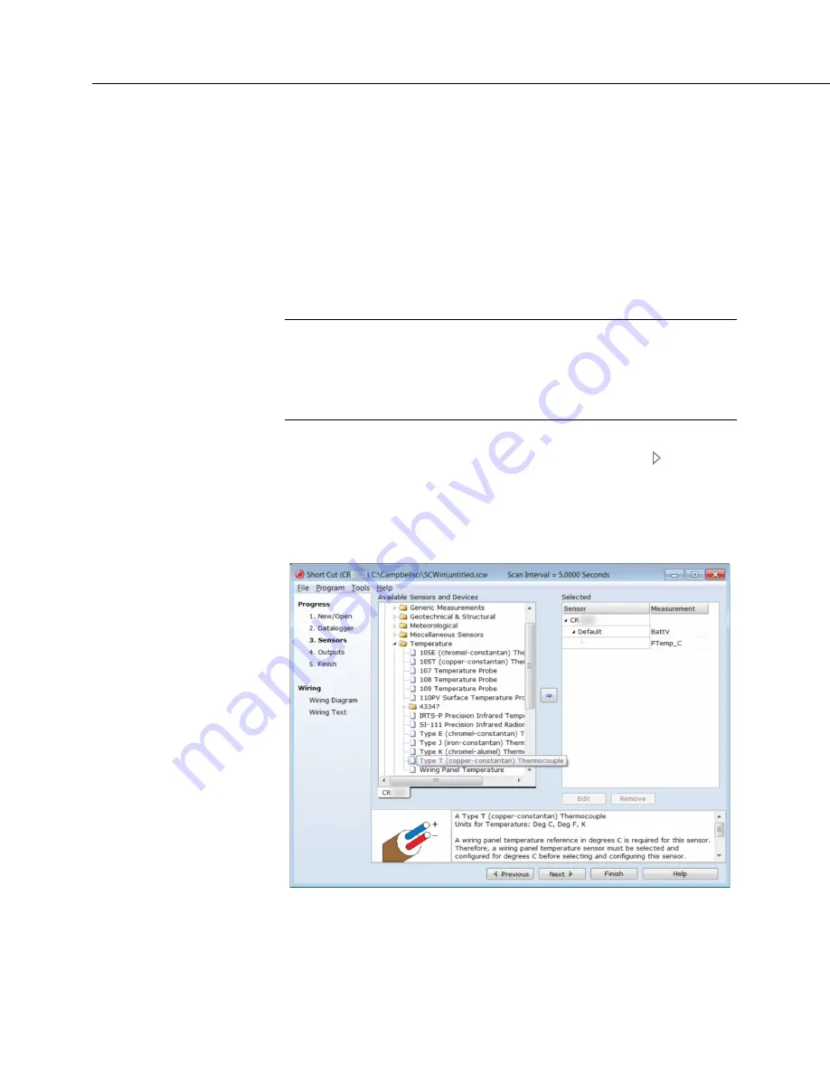
5. The next window displays
Available Sensors and Devices
as shown in the
following figure. Expand the
Sensors
folder by clicking on the symbol.
This shows several sub-folders. Expand the
Temperature
folder to view
available sensors. Note that a wiring panel temperature (
PTemp_C
in the
Selected
column) is selected by default.
FIGURE 3: Short Cut Temperature Sensor Folder
4.6.4.2 Procedure: (Short Cut Steps 6 to 7)
6. Double-click
Type T (copper-constantan) Thermocouple
to add it into the
Selected
column. A dialog window is presented with several fields. By
Summary of Contents for CR6 Series
Page 2: ......
Page 4: ......
Page 6: ......
Page 32: ......
Page 36: ......
Page 38: ......
Page 76: ...Section 5 Overview 76 FIGURE 20 Half Bridge Wiring Example Wind Vane Potentiometer ...
Page 80: ...Section 5 Overview 80 FIGURE 23 Pulse Input Wiring Example Anemometer ...
Page 136: ......
Page 454: ...Section 8 Operation 454 FIGURE 104 Narrow Sweep High Noise ...
Page 459: ...Section 8 Operation 459 FIGURE 106 Vibrating Wire Sensor Calibration Report ...
Page 535: ...Section 8 Operation 535 8 11 2 Data Display FIGURE 121 CR1000KD Displaying Data ...
Page 537: ...Section 8 Operation 537 FIGURE 123 CR1000KD Real Time Custom ...
Page 538: ...Section 8 Operation 538 8 11 2 3 Final Storage Data FIGURE 124 CR1000KD Final Storage Data ...
Page 539: ...Section 8 Operation 539 8 11 3 Run Stop Program FIGURE 125 CR1000KD Run Stop Program ...
Page 541: ...Section 8 Operation 541 FIGURE 127 CR1000KD File Edit ...
Page 546: ......
Page 552: ......
Page 610: ...Section 11 Glossary 610 FIGURE 137 Relationships of Accuracy Precision and Resolution ...
Page 612: ......
Page 648: ......
Page 650: ......
Page 688: ......
Page 689: ......


