Section 8. Operation
533
A keyboard is available for use with the CR6. See
Keyboard/Display — List
(p. 659)
for information on available keyboard/displays. This section illustrates the use of
the keyboard/display using default menus. Some keys have special functions as
outlined below.
Note
Although the keyboard/display is not required to operate the CR6, it
is a useful diagnostic and debugging tool.
8.11.1 Character Set
The keyboard display character set is accessed using one of the following three
procedures:
•
The 16 keys default to ▲, ▼, ◄, ►,
Home, PgUp, End, PgDn, Del,
and
Ins
.
•
To enter numbers, first press
Num Lock
.
Num Lock
stays set until
pressed again.
•
Above all keys, except
Num Lock
and
Shift
, are characters printed in
blue. To enter one of these characters, press
Shift
one to three times to
select the position of the character as shown above the key, then press the
key. For example, to enter
Y
, press
Shift
Shift
Shift
PgDn
.
•
To insert a space (
Spc
) or change case (
Cap
), press
Shift
one to two
times for the position, then press
BkSpc
.
•
To insert a character not printed on the keyboard, enter
Ins
, scroll down
to
Character
, press
Enter
, then press ▲, ▼, ◄, ► to scroll to the
desired character in the list that is presented, then press
Enter
.
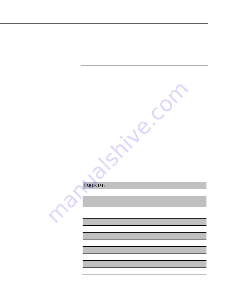
Special Keyboard/Display Key Functions
Key
Special Function
[2]
and
[8]
Navigate up and down through the menu list one line at
a time
[Enter]
Selects the line or toggles the option of the line the
cursor is on
[Esc]
Back up one level in the menu
[Home]
Move cursor to top of the list
[End]
Move cursor to bottom of the list
[Pg Up]
Move cursor up one screen
[Pg Dn]
Move cursor down one screen
[BkSpc]
Delete character to the left
[Shift]
Change alpha character selected
[Num Lock]
Change to numeric entry
Summary of Contents for CR6 Series
Page 2: ......
Page 4: ......
Page 6: ......
Page 32: ......
Page 36: ......
Page 38: ......
Page 76: ...Section 5 Overview 76 FIGURE 20 Half Bridge Wiring Example Wind Vane Potentiometer ...
Page 80: ...Section 5 Overview 80 FIGURE 23 Pulse Input Wiring Example Anemometer ...
Page 136: ......
Page 454: ...Section 8 Operation 454 FIGURE 104 Narrow Sweep High Noise ...
Page 459: ...Section 8 Operation 459 FIGURE 106 Vibrating Wire Sensor Calibration Report ...
Page 535: ...Section 8 Operation 535 8 11 2 Data Display FIGURE 121 CR1000KD Displaying Data ...
Page 537: ...Section 8 Operation 537 FIGURE 123 CR1000KD Real Time Custom ...
Page 538: ...Section 8 Operation 538 8 11 2 3 Final Storage Data FIGURE 124 CR1000KD Final Storage Data ...
Page 539: ...Section 8 Operation 539 8 11 3 Run Stop Program FIGURE 125 CR1000KD Run Stop Program ...
Page 541: ...Section 8 Operation 541 FIGURE 127 CR1000KD File Edit ...
Page 546: ......
Page 552: ......
Page 610: ...Section 11 Glossary 610 FIGURE 137 Relationships of Accuracy Precision and Resolution ...
Page 612: ......
Page 648: ......
Page 650: ......
Page 688: ......
Page 689: ......


