Section 7. Installation
147
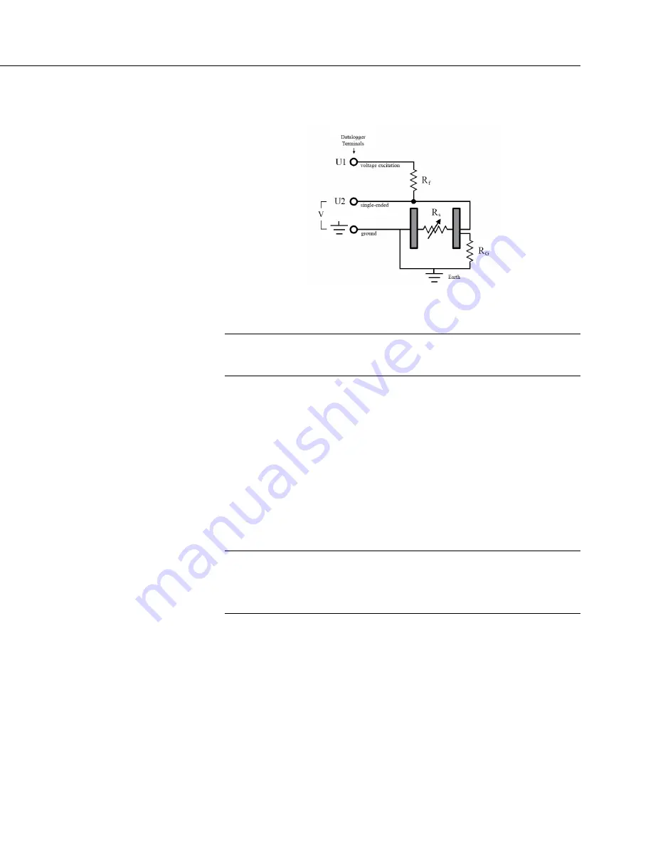
FIGURE 38: Model of a Ground Loop
with a Resistive Sensor
7.4
Protection from Moisture — Details
Protection from Moisture — Overview
(p. 95)
Protection from Moisture — Details
(p. 147)
Protection from Moisture — Products
(p. 670)
When humidity levels reach the dew point, condensation occurs and damage to
CR6 electronics can result. Effective humidity control is the responsibility of the
user. The CR6 module is protected by a packet of silica gel desiccant, which is
installed at the factory. This packet is replaced whenever the CR6 is repaired at
Campbell Scientific. The module should not normally be opened except to replace
the internal lithium battery.
Adequate desiccant should be placed in the instrumentation enclosure to provide
added protection.
7.5
CR6 Setup — Details
Related Topics:
•
CR6 Setup — Overview
(p. 93)
•
CR6 Setup — Details
(p. 147)
•
Status, Settings, and Data Table Information (Info Tables and Settings)
(p. 613)
Your new CR6 is already configured to communicate with Campbell Scientific
datalogger support software
(p. 97)
on the
USB
port, and over most comms links. If
you find that an older CR6 no longer communicates with these simple links,
update the operating system and do a full reset of the unit, as described in
Resetting the CR6
(p. 502).
Some applications, especially those implementing
TCP/IP features, may require changes to factory defaults.
Configuring modifies the firmware of the CR6. Programming modifies the CR6
CRBasic program. Settings are key to configuring the CR6.
Summary of Contents for CR6 Series
Page 2: ......
Page 4: ......
Page 6: ......
Page 32: ......
Page 36: ......
Page 38: ......
Page 76: ...Section 5 Overview 76 FIGURE 20 Half Bridge Wiring Example Wind Vane Potentiometer ...
Page 80: ...Section 5 Overview 80 FIGURE 23 Pulse Input Wiring Example Anemometer ...
Page 136: ......
Page 454: ...Section 8 Operation 454 FIGURE 104 Narrow Sweep High Noise ...
Page 459: ...Section 8 Operation 459 FIGURE 106 Vibrating Wire Sensor Calibration Report ...
Page 535: ...Section 8 Operation 535 8 11 2 Data Display FIGURE 121 CR1000KD Displaying Data ...
Page 537: ...Section 8 Operation 537 FIGURE 123 CR1000KD Real Time Custom ...
Page 538: ...Section 8 Operation 538 8 11 2 3 Final Storage Data FIGURE 124 CR1000KD Final Storage Data ...
Page 539: ...Section 8 Operation 539 8 11 3 Run Stop Program FIGURE 125 CR1000KD Run Stop Program ...
Page 541: ...Section 8 Operation 541 FIGURE 127 CR1000KD File Edit ...
Page 546: ......
Page 552: ......
Page 610: ...Section 11 Glossary 610 FIGURE 137 Relationships of Accuracy Precision and Resolution ...
Page 612: ......
Page 648: ......
Page 650: ......
Page 688: ......
Page 689: ......


