Appendix A. Info Tables and Settings
631
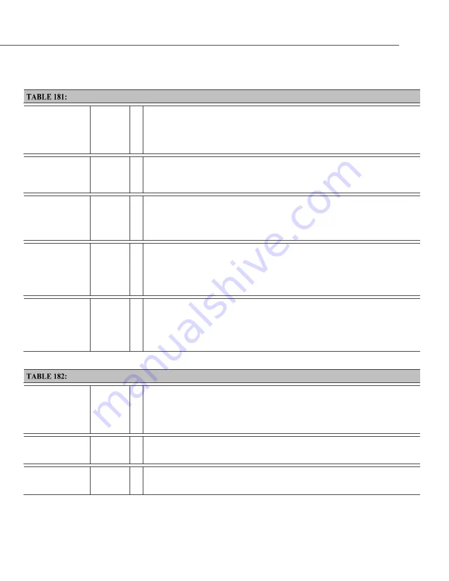
Info Tables and Settings: L
Keyword
Data Type
R
ead
O
nl
y
• Where to Find
Description
LastSlowScan()
NUMERI
C
Y
•
Status
table field: ≈37
Reports the last time a
SlowSequence
scan in the CRBasic program was executed. See
MaxSlowProcTime
SkippedSlowScan
(p. 638),
SlowProcTime
(p. 638).
LastSystemScan
NUMERI
C
Y
•
Status
table field: ≈36
Reports the time of the of the last auto (background) calibration, which runs in a hidden
slow-sequence type scan. See
MaxSystemProcTime
(p. 632),
SkippedSystemScan
(p. 638),
and
SystemProcTime
(p. 638).
LithiumBattery
Numeric Y
•
Station Status field:
Lithium Battery
•
Status
table field: ≈14
Voltage of the internal lithium battery. Updated only at CR6 power up. Normal range: 2.7
to 3.6 Vdc. Replace lithium battery if <2.7 Vdc. Updates when auto self-calibration
executes (once per minute).
Low12VCount
Numeric
•
Station Status field:
Number of times voltage has dropped below 12V
•
Status
table field 17
Counts the number of times the primary CR6 supply voltage drops below ≈9.8. Updates
with each
Status
table update. Range = 0 to 99. Reset by entering 0. Incremented prior to
scan (slow or fast) with measurements if the internal hardware signal is asserted.
Info Tables and Settings: M
Keyword
Data Type
R
ead
O
nl
y
• Where to Find
Description
MaxBuffDepth
Numeric
•
Status
table field: ≈36
Maximum number of buffers the CR6 will use to process lagged measurements.
MaxPacketSize
Numeric
•
Settings Editor:
Advanced |
Max Packet Size
Maximum number of bytes per data collection packet. Default = 1000.
Summary of Contents for CR6 Series
Page 2: ......
Page 4: ......
Page 6: ......
Page 32: ......
Page 36: ......
Page 38: ......
Page 76: ...Section 5 Overview 76 FIGURE 20 Half Bridge Wiring Example Wind Vane Potentiometer ...
Page 80: ...Section 5 Overview 80 FIGURE 23 Pulse Input Wiring Example Anemometer ...
Page 136: ......
Page 454: ...Section 8 Operation 454 FIGURE 104 Narrow Sweep High Noise ...
Page 459: ...Section 8 Operation 459 FIGURE 106 Vibrating Wire Sensor Calibration Report ...
Page 535: ...Section 8 Operation 535 8 11 2 Data Display FIGURE 121 CR1000KD Displaying Data ...
Page 537: ...Section 8 Operation 537 FIGURE 123 CR1000KD Real Time Custom ...
Page 538: ...Section 8 Operation 538 8 11 2 3 Final Storage Data FIGURE 124 CR1000KD Final Storage Data ...
Page 539: ...Section 8 Operation 539 8 11 3 Run Stop Program FIGURE 125 CR1000KD Run Stop Program ...
Page 541: ...Section 8 Operation 541 FIGURE 127 CR1000KD File Edit ...
Page 546: ......
Page 552: ......
Page 610: ...Section 11 Glossary 610 FIGURE 137 Relationships of Accuracy Precision and Resolution ...
Page 612: ......
Page 648: ......
Page 650: ......
Page 688: ......
Page 689: ......


