Section 5. Overview
72
Pulse Input Terminals and Measurements
Pulse Input
Terminal
Input Type
Data Option
CRBasic
Instruction
P
Terminal
•
Low-level ac
•
High-
frequency
•
Switch-closure
•
Counts
•
Frequency
•
Run
average of
frequency
PulseCount()
C
Terminal
•
Low-level ac
with
LLAC4
(p.
module
•
High-
frequency
•
Switch-closure
•
Counts
•
Frequency
•
Running
average of
frequency
•
Interval
•
Period
•
State
PulseCount()
TimerIO()
5.2.3.3 Pulse Sensor Wiring
Read More
See
Pulse Measurement Tips
(p. 377).
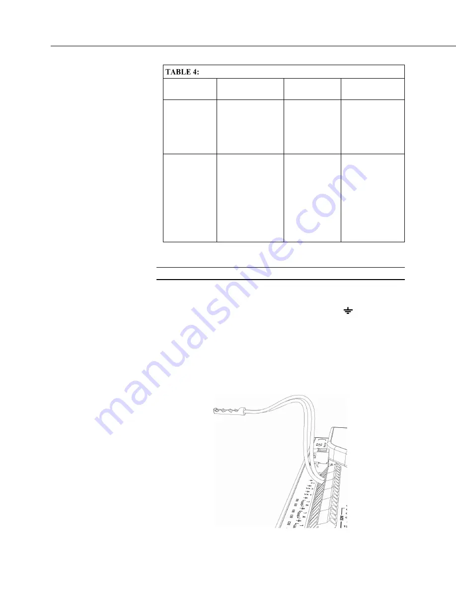
An example of a pulse sensor connection is illustrated in figure
Pulse Input
Wiring Example — Anemometer Switch
(p. 72).
Pulse sensors have two active
wires, one of which is ground. Connect the ground wire to a (signal ground)
terminal. Connect the other wire to a
P
terminal. Sometimes the sensor will
require power from the CR800, so there may be two added wires — one of which
will be power ground. Connect power ground to a
G
terminal. Do not confuse
the pulse wire with the positive power wire, or damage to the sensor or CR800
may result. Some switch closure sensors may require a pull-up resistor.
FIGURE 23: Pulse Input Wiring
Example — Anemometer
Summary of Contents for CR800 Series
Page 2: ......
Page 4: ......
Page 6: ......
Page 32: ......
Page 34: ......
Page 54: ......
Page 92: ......
Page 310: ......
Page 446: ...Section 8 Operation 446 8 11 2 Data Display FIGURE 100 CR1000KD Displaying Data ...
Page 448: ...Section 8 Operation 448 FIGURE 102 CR1000KD Real Time Custom ...
Page 449: ...Section 8 Operation 449 8 11 2 3 Final Storage Data FIGURE 103 CR1000KD Final Storage Data ...
Page 450: ...Section 8 Operation 450 8 11 3 Run Stop Program FIGURE 104 CR1000KD Run Stop Program ...
Page 452: ...Section 8 Operation 452 FIGURE 106 CR1000KD File Edit ...
Page 456: ......
Page 462: ......
Page 523: ...Section 11 Glossary 523 FIGURE 116 Relationships of Accuracy Precision and Resolution ...
Page 524: ......
Page 526: ......
Page 556: ......
Page 558: ......
Page 560: ......
Page 597: ......


