Appendix D. Servicing the CS110
D-4
At least 8 consecutive open (flag 1) initiated motor steps should
occur prior to arriving at the fully open position in order to
guarantee synchronization between the motor controller phase state
and the stepper-motor coils being energized.
Stator to shutter overlap exists in the fully opened and fully closed positions so
that slight shutter position variations do not alter the measured result. A fully
opened shutter will display symmetrical stator to shutter overlap, within the 1.8
°
stepper motor step size, on both edges of each of the 4 openings in the stator.
Once the shutter has been adjusted to the fully open position by means of flags 1
and 2, flag 3 is to be set high to execute a 25 closed step loop, which positions the
shutter in the fully closed position, which is the desired position for the Index
trim. No visible gaps between the stator and shutter blades should be visible in
the fully closed shutter position. Once in the fully closed position, hook an
oscilloscope or dc voltmeter to the
Index
test pin on the CS110 panel PCB. The
Ports and Flags button on the LoggerNet connect screen along with a graphical
display can also be used for trimming if the update interval is set to 50 ms.
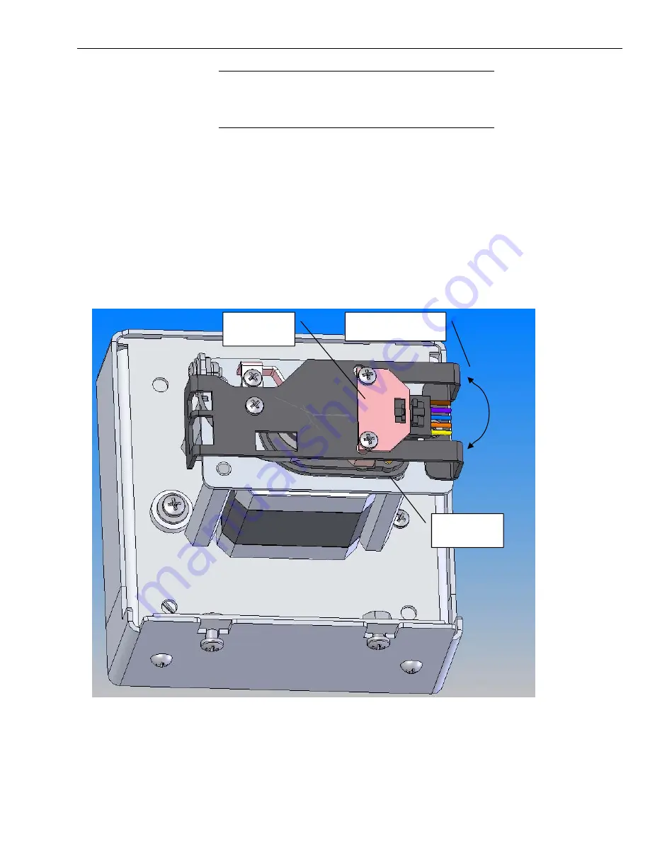
FIGURE D-2. CS110 Motor Assembly
NOTE
Motion of Encoder
Base Plate
Encoder Base
Plate
Connector
Locking Plate
Summary of Contents for CS110
Page 2: ......
Page 4: ......
Page 6: ......
Page 10: ...iv This is a blank page ...
Page 37: ...Instruction Manual 27 ...
Page 48: ......
Page 52: ...Appendix B CS110 Accessories This is a blank page B 2 ...
Page 56: ...Appendix C CS110 Connector Pin outs C 4 This is a blank page ...
Page 72: ...Appendix F Example CRBasic Programs This is a blank page F 4 ...
Page 78: ...Appendix G CS110 2 Metre CM10 Tripod Site This is a blank page G 6 ...
Page 85: ......

