CS120A and CS125 Visibility and Present Weather Sensors
17
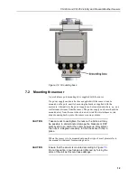
Finally secure the mount with the washers and nuts.
If the surface is not level and flat it may be necessary to add washers under the
base on one or more of the foundation screws.
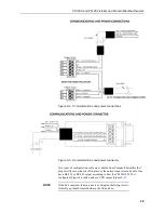
8. Sensor internal connectors’ description
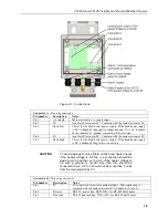
The sensor has four standard IP66 rated glands. The first gland is by default
used by the power/communications line. This comprises the 7-30 V for the
main electronics, and the serial communications wires. The sensor is supplied
with 5 m cable already connected.
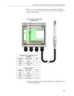
The second gland is used for the 24 V feeds for the hood heaters fitted with a 5
m cable.
Glands 3 and 4 are spare. If user alarms are connected they usually use gland 3
and if a CS215 is fitted this usually uses gland 4.
If you need to run cables through the cable glands follow these guidelines. If a
torque wrench is available use a torque of 2.5 Nm (do not over tighten).
Otherwise tighten with fingers as tight as possible and then add a further ¾ turn
with a 19 mm spanner (do not over tighten).
The glands are suitable for cables between 5 and 9 mm diameter.
If the power cable is incorrectly wired to the sensor then
damage can be done to the unit.
10 m is the longest length of the cable type supplied
recommended. In particular, additional RS-485
communication should be twisted pair. Please contact
Campbell Scientific if you wish to use a longer length of
cable.
CAUTION
CAUTION

