CS120A and CS125 Visibility and Present Weather Sensors
39
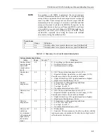
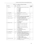
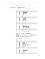
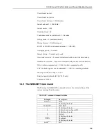
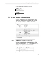
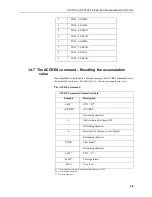
Table 13-1. User definable settings and descriptions
ID Name
Range
Description
Factory
default
8
Baud rate
0-6
Baud rate for the main RS-232/RS-485 interface
0 = 115200 bps
1 = 57600 bps
2 = 38400 bps
3 = 19200 bps
4 = 9600 bps
5 = 2400 bps
6 = 1200 bps
2
9
Serial number
-
Internal serial number for the sensor.
(
Read only)
-
10 Visibility Unit
M or F
Unit the visibility value will be presented as
M = metres
F = feet
M
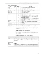
11 Message Interval
1-3600
Interval in seconds between outputs in continuous
mode. This value has no effect if polled mode has
been selected in ‘Measurement mode’
60
12 Measurement mode
0-1
Selects polled or continuous modes.
In continuous mode the sensor will output a string
in the format as set by ‘Message Format’ at
regular intervals as defined by ‘Continuous
Interval’.
0 = Continuous mode
1 = Polled mode
0
13 Message Format
0-12
Output message
0, 1 and 2 = Basic, partial or full visibility
messages
3, 4 and 5 = Basic, partial or full SYNOP
messages
6, 7 and 8 = Basic, partial or full METAR
messages
9, 10 and 11 = Generic basic, partial or full
SYNOP messages
12 = Custom message
5
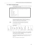
14 Serial port protocol
0-1
Selects the physical serial interface
0 = RS-232 mode
1 = RS-485 mode
0
15 Averaging period
1 or 10
The period of time that the visibility measurement
is averaged over. Either one minute or ten.
1
16 Sample timing
1-60
Used to define the time interval between sampling
the volume. It is recommended that this value is
left at one except when very low power demands
are needed. Note that 1s sample timing is needed
for present weather measurement. For example:
1 = Sample every second
2 = Sample one second in every two
3 = Sample one second in every three etc.
1
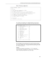
17 Dew heater override
0-1
0 = Allow the sensor to automatically control the
dew heaters
1 = Turn the dew heaters off
0


