background image

CRBasic Example 1: CR1000X program that measures the CS325DM using Modbus

SerialClose

(ComC7)

SerialOpen

(ComC7,19200,2,0,10000,4)

SerialFlush

(ComC7)

Scan

(1,Sec,0,0)

PanelTemp

(PTemp,15000)

Battery

(Batt_volt)

'CS325DM

ModbusMaster

(ModbusResult,ComC7,19200,18,3,Modbus_CS325DM,2,3,1,100,2)

CS325DM_ModbusResult = MBDecode(ModbusResult)

If

ModbusResult = 0

Then

CS325DM_Irradiance = Modbus_CS325DM(1)
CS325DM_Isc = Modbus_CS325DM(2)

'Short-Circuit Current

CS325DM_PVTemp = Modbus_CS325DM(3)

'PV Temperature

Else

CS325DM_Irradiance = NAN
CS325DM_Isc = NAN
CS325DM_PVTemp = NAN

EndIf
CallTable

OneMin

NextScan

EndProg

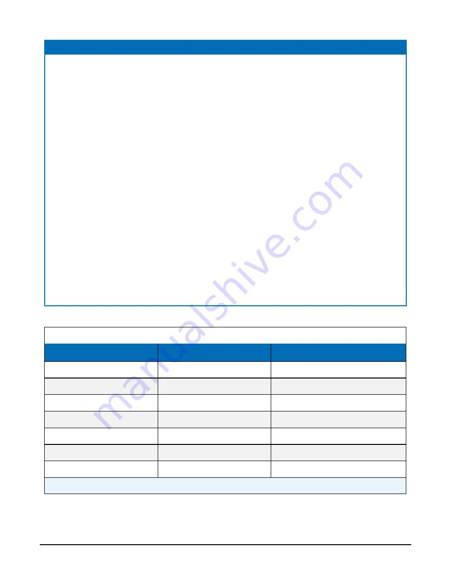
Table A-2: Analog example program wiring

Wire color

1

CR1000X terminal

Description

Brown

12V

12 VDC

White/brown stripe

G

Power and signal ground

Orange

Ground

Green

Ground

White/orange stripe

SE15

Irradiance input

White/green stripe

SE16

Temperature input

Clear

Shield

1

The white/blue striped and blue wires are not used for analog programming.

CS325DM Silicon Irradiance Reference Sensor

11

Summary of Contents for CS325DM

Page 1: ...Revision 07 2020 Copyright 2020 Campbell Scientific Inc...

Page 2: ...ial inspection 1 4 Overview 2 5 Specifications 2 6 Siting 4 7 Mounting 4 8 Wiring 4 9 Programming 6 9 1 RS 485 programming 6 9 1 1 Register map 6 9 2 Analog programming 7 10 Maintenance and troublesho...

Page 3: ...mize the potential for water entry to the sealed housing mount the CS325DM with the cable facing down or to the side l When opening the shipping package do not damage or cut the cable jacket If damage...

Page 4: ...ng and protection from the elements The M12 circular connector allows easy installation and cable replacement Features l Rugged design with wide temperature operating range l Analog and or digital out...

Page 5: ...tability 0 5 per year Mounting Four mounting holes with diameter 5 50 mm 0 217 in Dimensions 11 5 x 6 5 x 3 0 cm 4 5 x 2 6 x 1 2 in Weight 0 3 kg 0 6 lb Digital output Communications protocols Modbus...

Page 6: ...racket or U bolt on the crossarm and tighten the bolts or U bolt nuts 5 Use the bubble level and leveling bolts to level the sensor 6 If using the CM256 LP tilt to the correct azimuth and tighten bolt...

Page 7: ...nalog pin out wire color function and data logger connection Wire color1 Pin out Function Data logger connection White orange stripe 5 Irradiance input U configured for single ended analog input2 SE s...

Page 8: ...6 To do this the CRBasic program requires SerialOpen followed by ModbusMaster The SerialOpen instruction has the following syntax SerialOpen ComPort Baud Format TXDelay BufferSize Mode The Format para...

Page 9: ...r instruction for the temperature measurement CAUTION Nearby AC power lines electric pumps or motors can be a source of electrical noise If the sensor or data logger is located in an electrically nois...

Page 10: ...846 ASTM E824 or ASTM G207 by an accredited lab The recommended recalibration interval is 2 years The most common reason for communication failure for the CS325DM is because the sensor is not configur...

Page 11: ...programming CRBasic Example 1 CR1000X program that measures the CS325DM using Modbus CR1000X Series Data Logger CS325DM L RC18 Reference Cell Public PTemp Units PTemp C Public Batt_volt Units Batt_vo...

Page 12: ...ase 2 MBDecode Illegal data address Case 3 MBDecode Illegal data value Case 4 MBDecode Slave device failure Case 5 MBDecode Acknowledge error Case 6 MBDecode Slave device busy Case 8 MBDecode Memory p...

Page 13: ...DM_Isc Modbus_CS325DM 2 Short Circuit Current CS325DM_PVTemp Modbus_CS325DM 3 PV Temperature Else CS325DM_Irradiance NAN CS325DM_Isc NAN CS325DM_PVTemp NAN EndIf CallTable OneMin NextScan EndProg Tabl...

Page 14: ...00 C Public CS325DM_Analog2 Units CS325DM_Analog2 C DataTable OneMin 1 1 DataInterval 0 1 Min 10 Minimum 1 Batt_volt FP2 False False Sample 1 PTemp FP2 Average 1 CS325DM_Analog1 IEEE4 False Average 1...

Page 15: ...ther manufacturer s products that are resold by Campbell Scientific are warranted only to the limits extended by the original manufacturer Refer to www campbellsci com terms warranty for more informat...

Page 16: ...ion or Repair Reference number contact your CAMPBELL SCIENTIFIC regional office Please write the issued number clearly on the outside of the shipping container and ship as directed For all returns the...

Page 17: ...rohibit climbing by other persons Take reasonable precautions to secure tripod and tower sites from trespassers l Use only manufacturer recommended parts materials and tools Utility and Electrical l Y...

Page 18: ...nfo campbellsci fr www campbellsci fr Germany Location Phone Email Website Bremen Germany 49 0 421 460974 0 info campbellsci de www campbellsci de India Location Phone Email Website New Delhi DL India...

Reviews: