Appendix Title
22
9.5
Connection via RS232 port
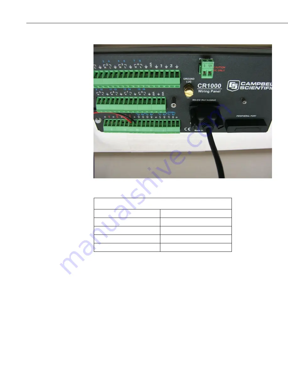
FIGURE 9-7. Modem connection to data logger RS232 port
TABLE 9-5. Parts Supplied with RS232 Modem Kit
Part number
Description
14162
Enclosure mounting kit for modem
RS232-INTELIMAX-CBL
DTE RS-232 male to RJ45 cable
MA-2015
Intelimax modem
ANT-ADAPTER-INTELIMAX
FME to SMA adaptor
Connect the RS232-INTELIMAX-CBL’s RJ45 connector to the socket on the
modem.
Connect the two tinned wires on this cable to the data logger. The red wire
connects to 12V and the black wire to the G terminal. The SW12 terminal can
be used instead of 12V however as it is a switched supply it needs to be
enabled in the datalogger program to function correctly.
Note that SW12 is a switched 12V supply and needs to be enabled in the data
logger program to function.
Insert the 9-pin end of the RS-232-INTELIMAX-CBL into the RS-232 (DCE)
connector on the logger.


