APPENDIX I. 21X PROM REPLACEMENT PROCEDURE
I-2
Panasonic
Panasonic
Panasonic
Pannasonic
1
2
3
4
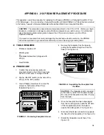
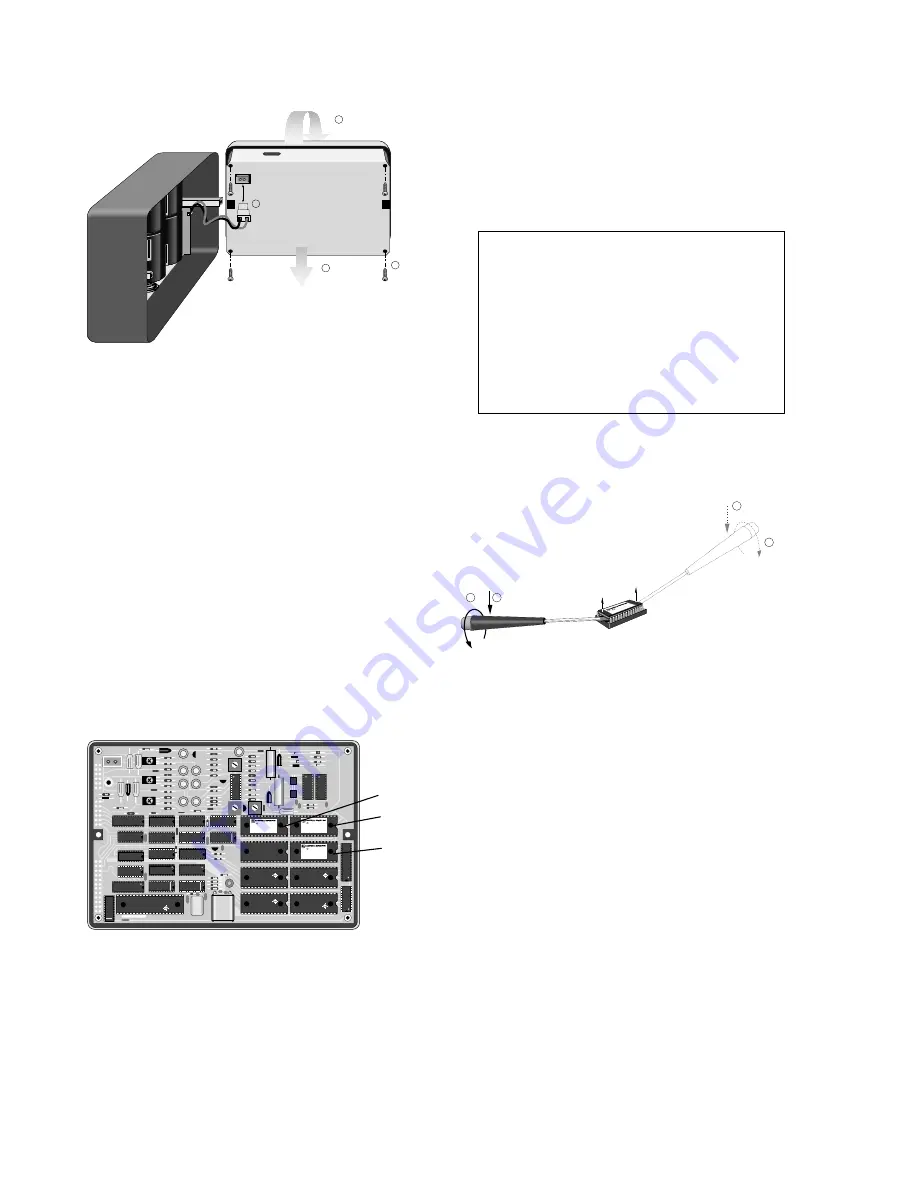
FIGURE I-3. Removing the Back Cover of
the Faceplate
8.
Use the Phillips screwdriver to remove the
four screws that hold the back cover to the
faceplate and printed circuit boards (
③
on
Figure I-3). The screws are attached to
spacers that may move once the screws
have been removed... so if something
rattles, don’t panic (yet).
9.
Remove the back cover of the faceplate (
④
on Figure I-3).
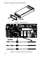
10. See Figure I-4 and the table below to
determine the PROM(s) you want to
replace. The installed PROMs all have a
notch on the right side. The replacement
PROMs must also be installed with the
notch on the right.
JAPAN 8547
HM6264LPI-15
U0013550
HM6264ALP-15
03012883
MALAYSIA 8803
KM6264AL-10
917 KOREA
HM6264LP-15
U0422880
MALAYSIA 8807
HM6264LP-15
U0422880
MALAYSIA 8807
CD4007UBE
RCA H 910
CD4053BE
RCA B 731
CD74HC574EX
RCA H 901
CD4020BEX
RCA H 840
CD4049BUEX
RCA H 845
CD47HC174EX
RCA H 745
CD74HC393EX
RCA H 901
CD74HC02EX
RCA H 923
CD47HC174EX
RCA H 745
CD74HC00EX
RCA H 923
CD74HC174EX
RCA H 745
CD4093BEX
RCA H 818
CD47HC138EX
RCA H 849
CD74HC574EX
RCA H 901
CD74HC10E
RCA H 836
MC74HC4078N
FFDS8929
CD74HC00EX
RCA H 923
6G1
J
HD63A03RP
JAPAN
CD4053BE
RCA B 731
CD4046BEX
RCA H .919
CD4504BEX
RCA H 910
CD4504BEX
RCA H 910
CD74HC138EX
RCA H 849
CD74HC573EX
RCA H 840
C
1994
ItemNo 6146
ObjsNo 01
C
1994
ItemNo 6145
ObjsNo 00
C
1994
ItemNo 6147
ObjsNo 02
FIGURE I-4. Inside the Faceplate
Firmware
Socket
Socket
Socket
A
B
C
OSX-0.1
6145-03
6146-05
6147-06
OSX-1.1
6145-03
6146-05
6160-05
OSX-2.1
6145-03
6146-05
6161-06
NOTE: Older 21X(L) Microloggers, pre
1986, were shipped with only two 4K RAM
chips (p/n 6116). When these Microloggers
are upgraded to new software PROMs, you
must replace the two 4K chips with five 8K
chips (p/n 6264). You may also need to
reset two jumpers. M15 must be jumpered
on the right set of pins and W20 and W27
must be jumpered on the left set of pins
(see Appendix E in the 21X manual).
11. Use a PROM puller to remove the PROM.
If you don’t have a PROM puller, use the
less elegant procedure described below:
ItemNo 6146
ObjslNo
C
1984
1
2
4
3
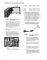
FIGURE I-5. Removing the PROM with a
Screwdriver
a) Insert the end of a small flat-bladed
screwdriver underneath the PROM,
then gently rotate the screwdriver to
slightly lift the PROM from the PROM
socket (
①
on Figure I-5).
b) Gently pry up the end of the PROM to
about 1/8” off the socket (
②
on Figure
I-5).
c)
Move the screwdriver to the other end
of the PROM and perform the same
procedure (
③
and
④
on Figure I-5).
d) Alternate prying the PROM from either
end. Lift the PROM approximately 1/8”
with each pry until the pins clear the
sockets and the PROM can be lifted out
of the socket.
B
A
C
Summary of Contents for DCP100
Page 4: ......
Page 8: ...TABLE OF CONTENTS IV This is a blank page ...
Page 26: ......
Page 28: ......
Page 30: ......
Page 44: ......
Page 45: ...J 1 APPENDIX J TELONICS MODEL TGT1 CERTIFICATION BY NOAA NESDIS ...
Page 46: ......
Page 47: ...This is a blank page ...


