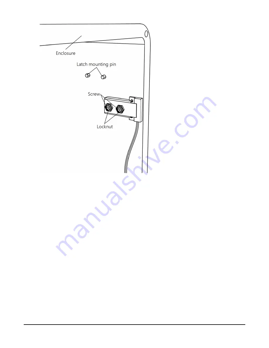
8. From the outside of the enclosure door, insert two screws through the new holes in the
enclosure door.
9. Place the assembled sensor magnet bracket over the two screws, making sure the sensor
magnet is aligned with the inside edge of the door. Secure the bracket in place with two
locknuts.
A.2 Example program
The door switch has two wires and is connected to the 5V terminal and a Control terminal. In this
example for the CR1000X terminal C1 is used.
The example program demonstrates two methods to record data. The first method maintains a
schedule, recording the door status at regular intervals. The second method adds a record to the
table only when the door is opened or closed.
The program also includes the option to turn on a Wi-Fi connection if the CR1000X is attached to
an NL241. The NL241 must be configured in the Device Configuration Utility to Create a Network
in the Wi-Fi tab under the Deployment tab.
Enclosures
29


