background image

SECTION 3.  ET INSTRUMENTATION INSTALLATION

3-3

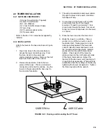
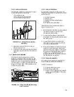
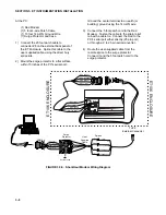
b) After determining the tilt angle,

loosen the two bolts that attach the
mounting bracket to the panel.
Adjust the angle, then tighten the
bolts.  Secure the lead wire to the
mast using wire ties.  Make
electrical connections as described
in 2b above.

3.1.3  AC POWER INSTALLATION

a) The AC power option includes a

120 VAC to 16 VAC.  The
transformer should be mounted
inside a user supplied junction box
according to local electrical codes.
Dangerous electrical accidents may
be avoided by locating the
transformer remotely and burying a
low voltage line to the station.  The
low voltage will carry up to 500 feet
on an 18 AWG power cable.

b) Shut off 110 VAC power at the

main breaker.  Connect the primary
leads of the transformer to 110
VAC following instructions provided
with the transformer.  Connect a
two conductor cable to the
secondary terminals of the
transformer.  Route the cable from
the transformer to the ET Enclosure
according to local electrical codes.

3.1.4  ENCLOSURE INSTALLATION

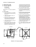
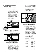
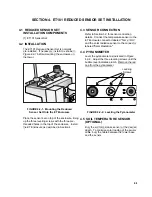
1.

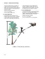
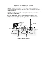
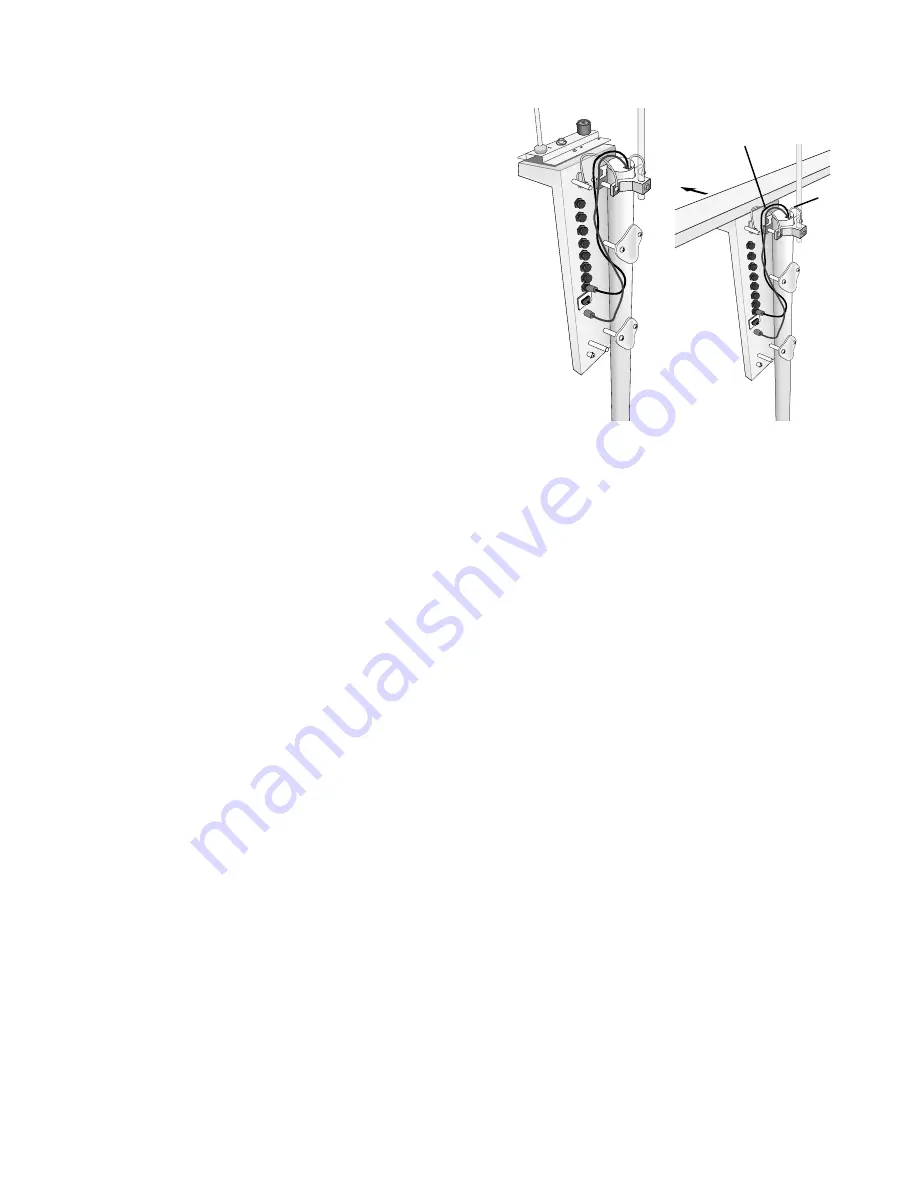
Mount and ground the ET enclosure on the
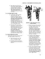
ET Tower as shown in Figure 3.1-4.

a) Place the enclosure low on the

tower.  Do not tighten clamps.

b) Install the sensor arm (ET106) or

reduced sensor set as described in
Section 4.


NORTH 

FIGURE 3.1-4.  Mounting and Grounding

the ET Enclosure

c)

Slide the enclosure to the top of the
ET tower.  Position it on the north
side of the tower (northern
hemisphere).  The top of the
enclosure should be flush with the
top of the tower, with the width of
the sensor arm extending above
the tower.  Tighten the clamps until
the enclosure is snug.  Do not over-
tighten since doing so may damage
the tower or enclosure.

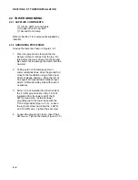
d) Carefully mount the lightning rod

and clamp to the top of the ET
Tower.  Clearance between the
clamp and the enclosure is
minimal.  Care should be taken not
to scratch the enclosure or sensor
assembly.  Strip 1 inch of insulation
from the top end of the 12 AWG
green tower ground wire, curl the
end and place the curled end under
the head of one of the lightning rod
clamp bolts.  Tighten the bolt.

e) Strip 1 inch of insulation from each

end of the 9 inch piece of 12 AWG
ground wire.  Insert one end into
the brass ground lug located at the
top back of the enclosure.  Curl the
other end and place under the head
of one of the lightning rod clamp
bolts.  Tighten the bolt.

9-inch

Ground

Wire

Tower

Ground

Wire

Summary of Contents for ET101

Page 1: ...INSTRUCTION MANUAL ET101 Weather Station Revision 12 97 C o p y r i g h t c 1 9 9 3 1 9 9 7 C a m p b e l l S c i e n t i f i c I n c ...

Page 2: ...her warranties expressed or implied including warranties of merchantability or fitness for a particular purpose CAMPBELL SCIENTIFIC INC is not liable for special indirect incidental or consequential damages Products may not be returned without prior authorization The following contact information is for US and International customers residing in countries served by Campbell Scientific Inc directly...

Page 3: ... 2 2 Tower Installation 2 3 Tower Grounding 3 ET INSTRUMENTATION INSTALLATION 3 1 3 1 Enclosure Datalogger Power Supply 3 2 Sensor Connection 3 3 Communication and Data Storage Peripherals 3 4 Sealing and Desiccating the Enclosure 4 ET101 REDUCED SENSOR SET INSTALLATION 4 1 4 1 Reduced Sensor Set Installation Components 4 2 Installation 4 3 Sensor Connection 4 4 Pyranometer 4 5 Soil Temperature Se...

Page 4: ...This is a blank page ...

Page 5: ...port to the field site 1 1 2 OUTDOORS Locate suitable site Section 1 Prepare tower or tripod base Section 2 Tripod and UT10 3 meter tower tower stations Raise tripod or tower Section 2 Install instrumentation enclosure Section 3 Install sensors Section 4 UT30 10 meter tower tower stations Install 3 to 10 meter level sensors Section 4 Raise tower Section 2 Install instrumentation enclosure Section ...

Page 6: ... materials 2 x 4 lumber stakes saw hammer nails etc Concrete trowel and edger Materials for UTDUK Duckbill Anchors Sledgehammer Highlift jack Chain to attach jack to anchor loops Materials for RFM18 Base 3 anchors appropriate for mounting surface 3 bolts and washers to secure base to anchors 1 2 2 TOOLS FOR INSTRUMENTATION AND MAINTENANCE All Towers Lock and key for enclosure Magnetic declination ...

Page 7: ... SPEED AND DIRECTION Wind sensors should be located over open level terrain and at a distance of at least ten times EPA the height of any nearby building tree or other obstruction as illustrated in Figure 1 3 1 Standard measurement heights 3 0 m 0 1 m recommended AASC 2 0 m 0 1 m 10 0 m 0 5 m optional AASC 10 0 m WMO and EPA 1 3 2 TEMPERATURE AND RELATIVE HUMIDITY Sensors should be located over an...

Page 8: ... weather station structures Reflective surfaces and sources of artificial radiation should be avoided The height at which the sensor is mounted is not critical 1 3 5 SOIL TEMPERATURE The measurement site for soil temperature should be at least 1 m2 and typical of the surface of interest The ground surface should be level with respect to the immediate area 10 m radius Standard measurement depths 10...

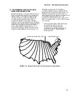
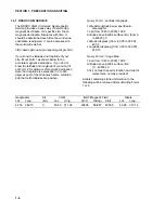
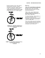
Page 9: ...ted States is shown in Figure 1 4 1 Declination angles east of True North are considered negative and are subtracted from 0 degrees to get True North as shown Figure 1 4 2 Declination angles west of True North are con sidered positive and are added to 0 degrees to get True North as shown in Figure 1 4 3 For example the declination for Logan Utah is 14 5 East True North is 360 14 5 or 345 5 as read...

Page 10: ...declination Note that longitude is expressed in 0 to 360 degrees east of the Greenwich prime meridian and that north latitudes are positive Query Form 1 Latitude Longitude Latitude Longitude below specified in Geographic Year from 1945 to 2000 1998 Altitude above Earth s surface km from 0 to 40000 0 Latitude degrees from 90 00 to 90 00 42 03 Longitude degrees from 0 00 to 360 00 248 15 Query Form ...

Page 11: ...to Get True North References 1 EPA 1987 On Site Meteorological Program Guidance for Regulatory Modeling Applications EPA 450 4 87 013 Office of Air Quality Planning and Standards Research Triangle Park North Carolina 27711 2 WMO 1983 Guide to Meteorological Instruments and Methods of Observation World Meteorological Organization No 8 5th edition Geneva Switzerland 3 The State Climatologist 1985 Pu...

Page 12: ......

Page 13: ...ate time Once attached they cannot be detached The ET Tower provides a support structure for mounting the ET101 and ET106 weather station components Figure 2 1 1 shows a typical ET Tower installation option The tower is designed to withstand winds of 100 mph The lightning rod assembly is attached after the instrumentation enclosure is installed Section 3 1 Transformer User Supplied Junction Box 11...

Page 14: ...he conduit Make certain the cavity points in the direction from which power and communications cables will come 6 Center the form over the hole Adjacent to the form drive four stakes into the soil Secure the leveled form to the stakes with the 8p nails 7 Cap the ends of the conduit with duct tape Position the conduit and wire into place by securing the wire to nails in the form 8 Fill the hole and...

Page 15: ...ugh the tower and conduit Electrical fish tape will help 4 Cut and save a 9 inch piece of 12 AWG ground wire from the 12 foot length provided Thread the remaining 11 foot ground wire through the tower Secure all wiring so it does not slip back into the tower or conduit 5 Place the tower cap over the tower end 6 Raise the tower on a still day Place a washer on top of the two nuts on each foundation...

Page 16: ... Taking care not to damage power or communications lines drive the ground rod close to the foundation using a fence post driver or sledge hammer Drive the rod at an angle if an impenetrable hardpan layer exists Soften hard clay soils with water if necessary 3 Strip 1 inch of insulation from both ends of the 4 AWG ground cable Strip 1 inch of insulation from the lower end of the 14 AWG ground wire ...

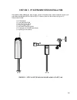
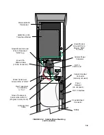
Page 17: ... are mounted in the ET enclosure at the locations shown in Figure 3 1 Components include 1 ET Enclosure 1 4 unit Desiccant Pack 1 Flat Point Screw Driver 1 Power Supply Option 1 Telecommunications Option 1 9 inch piece of 12 AWG ground wire 1 Lightning rod and clamp Logan Utah MADE IN USA FIGURE 3 1 ET101 and ET106 Instrumentation Mounted on the ET Tower ET101 ET106 ...

Page 18: ...d with the rechargeable battery at all times In either case power is routed through the Heyco fitting on the enclosure back and connected to the CHG ports by depressing connector levers Polarity of the CHG connection does not matter Install the rechargeable battery and plug the battery lead into the connector labeled LA 3 1 2 SOLAR PANEL INSTALLATION FIGURE 3 1 3 Solar Panel Mounting a Mount the s...

Page 19: ...r as shown in Figure 3 1 4 a Place the enclosure low on the tower Do not tighten clamps b Install the sensor arm ET106 or reduced sensor set as described in Section 4 NORTH FIGURE 3 1 4 Mounting and Grounding the ET Enclosure c Slide the enclosure to the top of the ET tower Position it on the north side of the tower northern hemisphere The top of the enclosure should be flush with the top of the t...

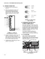
Page 20: ...witch settings as shown in Figure 3 2 2 if necessary Open 604 Ohm 100 Ohm LI1200X LI190SB LI200S Open 1 K Open CS500 HMP45C CS500 HMP45C HMP35C Open SW 12V 5V HMP35C FIGURE 3 2 2 Default Sensor Switch Settings 3 3 COMMUNICATION AND DATA STORAGE PERIPHERALS One communications kit can be mounted to the ET Enclosure back plate Communications kits ordered with the ET Enclosure are pre mounted and pre ...

Page 21: ...r must be coordinated with your local cellular provider Cellular service enables communication between the ET Enclosure and the Hayes compatible modem at your PC without hardwire connections The cellular transceiver kit must be purchased with one of the phone modem kits 3 3 2 1 Internal Installation For installation inside the ET Enclosure the following components are provided in the cell phone mo...

Page 22: ...not used Power Indicator do not press RJ11C Interface Coax Bulkhead Connector Battery Motorola M600 Transceiver COM200 or VS1 Telephone Modem Green Modem Ground Wire to Recessed GND Lug Blue 9 Pin Ribbon Cable 1 Extra Connector Black Transceiver Ground Wire to GND Red Transceiver 12 Volt Wire to 12 V Green Transceiver Control Wire to RCV Program Control Port 2 Antenna Coax Cable ...

Page 23: ...he following components are provided in the short haul modem kit 1 SC932C Interface 1 Rad Modem 1 Rad SC932C Mounting Bracket 4 Screws 1 12 inch 4 wire patch cable Install the short haul modems as shown in Figure 3 3 4 and 3 3 5 1 Mount the Rad SC932C mounting bracket into the ET Enclosure with the 3 pre threaded screws provided 2 Connect the Rad Modem and SC932C Strap them into the mounting brack...

Page 24: ...o the Rad Modem Fasten the cable to the strain relief tab with a cable tie Connect the Rad to the PC s serial port either directly 25 pin port or through a 9 to 25 pin serial converter 4 Route the user supplied cable from the remote splice to the surge protector Connect it and the 5 foot patch cord to the surge protector RCV white RCV black RCV green RCV red XMT red XMT green XMT black XMT white R...

Page 25: ...ag Place it under the desiccant strap just before leaving the station 2 Be sure to close the enclosure hasp securely A padlock may be used on the latch for extra security DO NOT EAT UNITED DESICCANTS GATES 101CHRISTINE BELEN NEW MEXICO 87002 DESI PAK SPECIFICATION MIL D 3464 TYPE I II REACTIVATION TIME IN BAG 16 HOURS AT 250 F DESICCANT ACTIVATED BAGGED FOR CONTENTS 4 UNITS PACKAGE USE AND STATIC ...

Page 26: ......

Page 27: ...nstall the ET Enclosure as described in Section 4 4 3 SENSOR CONNECTION Refer to Section 3 2 for sensor connection details Connect the temperature sensor to the ET Enclosure connector labeled Temp RH and the solar radiation sensor to the connector labeled Solar Radiation 4 4 PYRANOMETER Level the pyranometer as indicated in Figure 4 2 2 Adjust the three leveling screws until the bubble level indic...

Page 28: ...40 to 122 F 5 Small Cylinder Temp C 40 to 50 C 6 Solar Radiation kW m 2 0 to 1 2 kW m 2 7 Fixed Wind Speed mph 0 to 110 mph 9 Big Cylinder Temp C 40 to 50 C 10 Soil Temperature 107 40 to 50 C or 40 to 122 F 28 Enclosure RH 0 to 30 when sealed for several hours 4 7 SENSOR SCHEMATICS Schematics of ET101 sensors and associated connectors are provided in Figures 4 1 and 4 2 for help in troubleshooting...

Page 29: ...ture Probe Connector Pin Datalogger Not Used Excitation Top Temperature Thermistor Thermistor 1K OHM 1K OHM 249K OHM 249K OHM Analog Ground Bottom Temperature Shield 4 3 1 5 2 6 E1 1H AG 1L G 1 2 3 4 5 6 FIGURE 4 2 Schematic of CS200 Air Temperature Probe and Connector 7 ...

Page 30: ......

Page 31: ...120 manual 2 Create the ET datalogger program by clicking your mouse cursor on the main screen Edit then on Create Station Program Edit Create Station Program Follow the prompts until you return to the main screen 3 Click on Edit Communications Param to set up the PC to ET telecommunications link Check the link by attempting to set the clock Maintenance Set Clock 4 Download the program by selectin...

Page 32: ......

Page 33: ... be used to maintain power to the datalogger when changing batteries otherwise the clock program and data will be lost refer to the Installation Section of the datalogger s Operator s Manual for details When not in use remove the eight cells to eliminate potential corrosion of the contact points and store in a cool dry place Rechargeable power supplies should be connected to an AC transformer or u...

Page 34: ... 12 V and G terminals the voltage must be between 9 6 and 16 VDC C Disconnect any sensor or peripheral wires connected to the 5 V and 12 V terminals D Disconnect any communications or storage peripherals from the datalogger E Reset the datalogger by turning the power switch to OFF then to ON or disconnecting and reconnecting the battery F If still no response call Campbell Scientific 6 2 2 NO RESP...

Page 35: ...umbered sequentially starting at 1H i e 1L is single ended channel 2 C Make sure the Range parameter in the measurement instruction covers the full scale voltage output by the sensor 6 2 4 UNREASONABLE RESULTS DISPLAYED IN AN INPUT LOCATION A Inspect the sensor for damage and or contamination B Make sure the sensor is properly wired to the datalogger C Check the multiplier and offset parameters in...

Page 36: ......

Page 37: ...This is a blank page ...

Page 38: ... campbellsci com br suporte campbellsci com br Campbell Scientific Canada Corp CSC 11564 149th Street NW Edmonton Alberta T5M 1W7 CANADA www campbellsci ca dataloggers campbellsci ca Campbell Scientific Ltd CSL Campbell Park 80 Hathern Road Shepshed Loughborough LE12 9GX UNITED KINGDOM www campbellsci co uk sales campbellsci co uk Campbell Scientific Ltd France Miniparc du Verger Bat H 1 rue de Te...

Reviews: