background image

7.2 GRANITE modules

GRANITE modules mount in the CHASSIS using pre-installed anti-vibration screws; they simply
need to be tightened when GRANITE modules are installed. If a screw is damaged, or the anti-
vibration patch wears off, it may be replaced.

NOTE:
When removing a mounting screw entirely, resistance may be felt as the screw is backed out.
Similarly, when reinstalling, there will be some resistance; be certain not to cross thread the
screw.

7.3 Orientation

The CHASSIS is designed to sit on a horizontal surface or be mounted such that the GRANITE
mounting plane is horizontal, whether sitting on a flat surface or installed in a rack system.
Although there are bumpers on the sides, the CHASSIS should not normally be placed in
operation on its side without provision to prevent tipping and falling.

7.4 Rackmount

Attach the CHASSIS to sliding extendable rails in a 48 cm (19 in) wide server rack using the
Rackmount, Slide-Rail Kit for GRANITE CHASSIS.

Recommended installation sequence:

1. Loosely mount slide rails to rack interface brackets using #8-32 screws and nuts.

2. Mount slide rails with brackets to server rack uprights using #10-32 screws and cage nuts.

3. Attach CHASSIS rackmount bracket to slide rails using #8-32 hardware.

4. Align bracket to rails and tighten screws.

5. Remove eight rubber bumpers from both sides of the CHASSIS.

6. Carefully set CHASSIS on rackmount brackets (like a shelf).

7. Install 8 #10-32 x 0.250 truss-head screws through rackmount bracket into the CHASSIS and

tighten.

Verify the CHASSIS slides in and out of rack smoothly with no interference; adjust and re-tighten
fasteners as needed.

GRANITE CHASSIS

12

Summary of Contents for GRANITE

Page 1: ...04 2021 Copyright 2021 Campbell Scientific Inc GRANITE CHASSIS Chassis for GRANITE Data Acquisition Systems ...

Page 2: ...tions 9 6 2 Electrical specifications 10 7 Mounting and installation 11 7 1 Recommended module locations 11 7 2 GRANITE modules 12 7 3 Orientation 12 7 4 Rackmount 12 7 5 Tie downs 13 8 Wiring 14 8 1 Grounding CHASSIS 14 8 2 Power bus 14 8 3 Routing user installed cables 16 9 Top and rear panels 16 10 Linking multiple CHASSIS 18 11 Maintenance 18 11 1 Battery maintenance 19 Table of Contents i ...

Page 3: ...stationary Power can be supplied by AC or DC sources such as solar or rackmounted wall power Configuration versatility suits many demanding applications and operational environments NOTE The terms DAQ and data logger may be used interchangeably throughout this manual While there may be subtle differences depending on context or opinion ultimately a DAQ or data logger is the primary controller of a...

Page 4: ...lled with only a DC power source for example a solar pannel NOTE Use the largest gauge wire available up to 8 AWG for grounding NOTE To avoid ground loops only allow a single path to ground The second grounding lug is intended to connect subsequent devices that need to be grounded such as one or more daisy chained CHASSIS or GRANITE modules that are mounted external to the CHASSIS l Always use saf...

Page 5: ...able 2 1 Symbols used on the CHASSIS Symbol Description Direct current Alternating current Earth ground terminal Protective conductor terminal Caution possibility of electric shock 3 Initial inspection 3 1 Inspect packaging Upon receiving the GRANITE CHASSIS inspect the packaging and contents for damage Claims for shipping damage must be filed with the shipping company Locate the order packing sli...

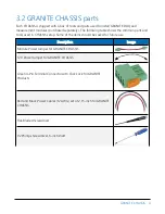
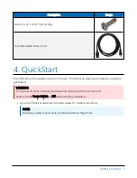
Page 6: ...s and tools used in CHASSIS setup Some of the items should be saved for future use Description Image Module Power Jumper for GRANITE CHASSIS 12 V Power Jumper for GRANITE CHASSIS Green 4 Pin Terminal Connector with Click Lock for GRANITE Products Red and Black Power Cables 12 AWG set of 2 15 inch for GRANITE CHASSIS Flat Bladed Screwdriver 2 Phillips Screwdriver 6 inch shaft GRANITE CHASSIS 4 ...

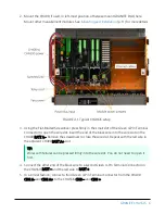
Page 7: ...wing steps are provided as a guide to get started WARNING Turn power off while installing hardware and making electrical connections Set the CH400 Power Switch to Off before starting installation 1 Use a 2 Phillips Screwdriver to loosen screws for module mounting NOTE Mounting screws only need to be loosened two to three turns GRANITE CHASSIS 5 ...

Page 8: ...nd of the black wire into the wire slot on the CH400 BATT A Remove the screwdriver to close the wire slot Repeat with the red wire in the adjacent CH400 BATT A slot TIP Wires with ferrules can be pressed firmly into the wire slot You do not need to open it first 4 Connect the other end of the black wire to a second Green 4 Pin Terminal Connector on the CHASSIS BATT and the red wire to BATT 5 In a ...

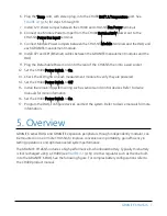
Page 9: ... to verify they are powered 14 Set the CH400 Power Switch to Off 15 Install the remaining system wiring such as sensors and control devices Refer to device manuals for more information 16 Set the CH400 Power Switch to On 17 Program the DAQ configure devices and test the system Refer to device manuals for more information 5 Overview GRANITE series DAQs and GRANITE expansion peripherals though indep...

Page 10: ...wer configuration options o 36 VDC 600 W AC DC Power Supply o 24 VDC 250 W AC DC Power Supply o No internal power supply l User customizable top and rear panels l Configurable layout l High performance operations even at maximum operating temperatures GRANITE CHASSIS 8 ...

Page 11: ... With bumpers Without bumpers Width W 45 4 cm 17 98 in 44 8 cm 17 65 in Depth D 31 0 cm 12 21 in 31 0 cm 12 21 in Height H 25 3 cm 9 95 in 24 4 cm 9 61 in Weight CHASSIS only no battery 10 6 kg 23 3 lb Battery 3 0 kg 6 7 lb CHASSIS with GRANITE modules typical 20 4 kg 45 0 lb GRANITE CHASSIS 9 ...

Page 12: ... 50 60 Hz DC output power from power supply 36V 36 VDC 16 7 A max 600 Watts 24V 24 VDC 10 4 A max 250 Watts AC input connector as applicable IEC C14 AC input cable as applicable 100 240 VAC 8 A max 50 60 Hz NEMA 5 15P to IEC C13 Current drain CHASSIS only modules not included Fans 250 mA 3 Watts per fan when running thermostat controlled Illumination LED 30 mA when on Battery 12 VDC 8 Ah AGM seale...

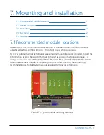
Page 13: ...m front to rear when fans are on To deliver optimal thermal performance where maximum heat dissipation is needed mount the CH400 when used in the position furthest to the left as shown in the following image For wiring convenience mount the DAQ GRANITE 6 GRANITE 9 GRANITE 10 next to the CH400 Mount measurement modules in remaining locations When observing these mounting recommendations the battery...

Page 14: ...y be placed in operation on its side without provision to prevent tipping and falling 7 4 Rackmount Attach the CHASSIS to sliding extendable rails in a 48 cm 19 in wide server rack using the Rackmount Slide Rail Kit for GRANITE CHASSIS Recommended installation sequence 1 Loosely mount slide rails to rack interface brackets using 8 32 screws and nuts 2 Mount slide rails with brackets to server rack...

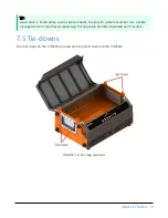
Page 15: ...to allow for cable movement Use a cable management arm purchased separately to keep cable bundles organized and movable 7 5 Tie downs Four ear loops on the CHASSIS provide anchor points to secure the CHASSIS FIGURE 7 2 Ear loop locations GRANITE CHASSIS 13 ...

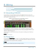
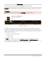
Page 16: ...equately grounded through the ground pin on the AC plug When using multiple wall plugged CHASSIS do not daisy chain the CHASSIS grounds Connect at least one CHASSIS ground lug to vehicle ground or earth ground for stationary deployments See also Precautions p 2 8 2 Power bus Terminals labeled Module Power are common The power voltage plugged into one of these will be distributed along this power b...

Page 17: ...ower bus The Green 4 Pin Terminal Connector connects two components the left side to the internal CHASSIS 12 V AGM battery and the right side to internal power when there is an AC DC power supply present The output voltage on this side is the same as indicated in red text on the label It will be one of the following l 0 VDC no internal power supply l 24 VDC nominal l 36 VDC nominal The Temp cord w...

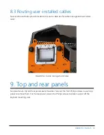
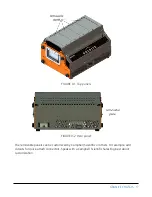
Page 18: ...gement and strain relief FIGURE 8 2 Cable management holes 9 Top and rear panels Solid aluminum top and rear panels are removable Take out the four Phillips screws in each top panel to remove them For the rear panel loosen the Phillips screws to slide it up and off the keyhole mounting slots GRANITE CHASSIS 16 ...

Page 19: ...RE 9 2 Rear panel The removable panels can be customized by Campbell Scientific or others For example add cutouts for quick attach connectors Speak with a Campbell Scientific Sales Engineer about customization GRANITE CHASSIS 17 ...

Page 20: ... the other end to the second CHASSIS Power Bus Input terminal 4 Set the CH400 Power Switch to On 11 Maintenance Keep the GRANITE CHASSIS clean and dry The GRANITE CHASSIS can be expected to deliver many years of reliable service Eventual maintenance includes battery and cooling fan replacements See Battery maintenance p 19 Only access hardware and fasteners with Phillips heads Star or torx heads s...

Page 21: ...attery that is disconnected from all loads will typically maintain its charge for up to six months Recharge the CHASSIS battery before use when it has been left for six months or more without a charging source Battery life is a function of many variables including number of charge cycles depth of discharge and operating temperatures NOTE Before replacing the CHASSIS battery collect all data from t...

Page 22: ...ry removed from drawer 8 Install a new battery 9 Slide the drawer in connecting the battery plug when about half way then slide it the rest of the way in 10 Ensure the knob seats again completely 11 Plug the Green 4 Pin Terminal Connector back in 12 Plug in the Detachable Power Cord if present GRANITE CHASSIS 20 ...

Page 23: ...Other manufacturer s products that are resold by Campbell Scientific are warranted only to the limits extended by the original manufacturer Refer to www campbellsci com terms warranty for more information CAMPBELL SCIENTIFIC EXPRESSLY DISCLAIMS AND EXCLUDES ANY IMPLIED WARRANTIES OF MERCHANTABILITY OR FITNESS FOR A PARTICULAR PURPOSE Campbell Scientific hereby disclaims to the fullest extent allow...

Page 24: ...tion or Repair Reference number contact your CAMPBELL SCIENTIFIC regional office Please write the issued number clearly on the outside of the shipping container and ship as directed For all returns the customer must provide a Statement of Product Cleanliness and Decontamination or Declaration of Hazardous Material and Decontamination form and comply with the requirements specified in it The form i...

Page 25: ...prohibit climbing by other persons Take reasonable precautions to secure tripod and tower sites from trespassers l Use only manufacturer recommended parts materials and tools Utility and Electrical l You can be killed or sustain serious bodily injury if the tripod tower or attachments you are installing constructing using or maintaining or a tool stake or anchor come in contact with overhead or un...

Page 26: ... info campbellsci fr www campbellsci fr Germany Location Phone Email Website Bremen Germany 49 0 421 460974 0 info campbellsci de www campbellsci de India Location Phone Email Website New Delhi DL India 91 11 46500481 482 info campbellsci in www campbellsci in South Africa Location Phone Email Website Stellenbosch South Africa 27 21 8809960 sales campbellsci co za www campbellsci co za Spain Locat...

Reviews: