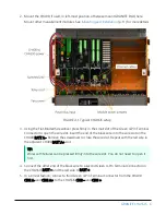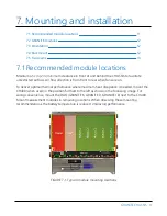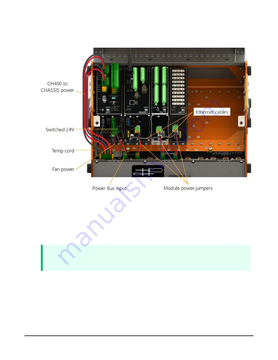
2. Mount the CH400, if used, in left-most position, otherwise mount GRANITE DAQ here.
Mount other measurement modules. See
(p. 11) for more details.
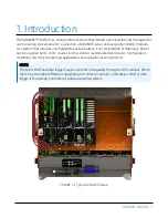
FIGURE 4-1. Typical CHASSIS setup
3. Using the Flat-Bladed Screwdriver press firmly in the small slot of the Green 4-Pin Terminal
Connector to open the wire slot. Insert the end of the black wire into the wire slot on the
CH400 BATT A–. Remove the screwdriver to close the wire slot. Repeat with the red wire in
the adjacent CH400 BATT A+ slot.
TIP:
Wires with ferrules can be pressed firmly into the wire slot. You do not need to open it
first.
4. Connect the other end of the black wire to a second Green 4-Pin Terminal Connector on
the CHASSIS BATT – and the red wire to BATT +.
5. In a similar fashion, connect a third Green 4-Pin Terminal Connector from the CH400
CHG A- and CHG A+ to the CHASSIS CHG – and CHG +.
GRANITE CHASSIS
6


