background image

NL100/105 Network Link Interface 

3.2.3  MD485 Connection from NL100/105 to Datalogger 

Campbell Scientific's RS485 communication device, the MD485, can be 
attached to an NL100/105 to provide a communication link to one or more 
dataloggers. The MD485 has three communication ports: RS485 (two 
terminals but the same physical port), CS I/O, and RS232. It can be configured 
for communication on any two of its three ports at one time. The most typical 
use of the MD485 is to set up a network of dataloggers linked together in an 
RS485 network. However, you can also attach a datalogger or other 
compatible peripheral to the CS I/O port or the RS-232 port of the MD485.  

The MD485 can be configured to communicate in a transparent (point to point) 
mode, as an MD9 emulator, or as a peripheral in a PakBus network. For 
transparent or PakBus communication, the MD485 is attached to the 
NL100/105's RS485 port using a 3-wire shielded cable (i.e., a 2 twisted pair 
shielded cable). For MD9 emulation, at least two MD485s are required. One 
MD485 is attached to the NL100/105's RS232 port using an SC12 cable. This 
MD485 acts as a base MD9 device, since the NL100/105 is, in itself, not 
capable of MD9 communication. A second MD485 is attached to each of the 
dataloggers. 

An appendix in the MD485 manual provides complete information on setting 
up the NL100/105 and the MD485s for each of the above configurations, along 
with information on the settings used in LoggerNet. 

3.2.4  RF Connection from NL100/105 to Datalogger 

Interfacing the NL100/105 to an RF Base station enables wireless 
communication to remote datalogger stations over a TCP/IP network.  The 
preferred configuration uses the NL100/105's RS-232 port (DTE) for 
connection to the RF Base as follows: 

For connecting to the RS-232 port (DCE) of the RF4xx series or RF450 Spread 
Spectrum radios, a standard RS-232 serial cable (CSI# 10873 or equivalent) is 
used.

For connecting to the RS-232 port (DTE) on an RF500M RF Modem, a null-
modem RS-232 serial cable (CSI# 13657 or equivalent) must be used.  If 
connecting to the CSI/O port on the RF500M, an SC532A 9-Pin Peripheral to 
RS-232 interface adapter and standard serial cables are required. 

When connecting to an RF310B Base Station or its predecessors 
(or directly to an  RF310M RF Modem via an SC532A), the RTS 
line in the standard RS-232 serial cable (pin seven on a 9-pin 
connector or pin four on a 25-pin connector) must be disabled.  
This is done to prevent driving the SDE signal (pin 6) on the RF 
Modem's CSI/O port high and inhibiting the ME communication 
cycle.

NOTE

If circumstances should require the utilization of the NL100/105's CS I/O port 
for connection to an RF base, please contact a Campbell Scientific 
Applications Engineer for information about how this might be achieved. 

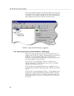
The configuration of the Setup window in LoggerNet will vary depending on 
the equipment and configuration settings employed.  Please consult the 
relevant manual(s) for configuration specifics.  Figure 5 depicts the LoggerNet 

22

Summary of Contents for NL100

Page 1: ...ision 12 10 NL100 NETWORK LINK INTERFACE POWER RS485 Logan Utah RS485 CS I O CS I O RS232 RS232 LAN LINK 10 BASE T MADE IN USA SN 10 BASE T L I N K L A N G 12V C o p y r i g h t 2 0 0 0 2 0 1 0 C a m...

Page 2: ...glect accidents of nature or shipping damage This warranty is in lieu of all other warranties expressed or implied including warranties of merchantability or fitness for a particular purpose CSC is no...

Page 3: ...s Area 1 in2 square inch 645 mm2 Length 1 in inch 25 4 mm 1 ft foot 304 8 mm 1 yard 0 914 m 1 mile 1 609 km Mass 1 oz ounce 28 35 g 1 lb pound weight 0 454 kg Pressure 1 psi lb in2 68 95 mb Volume 1 U...

Page 4: ...t 8 2 4 3 1 TLink Config 8 2 4 3 2 RS485 Config 9 2 4 3 3 CS I O Config 10 2 4 3 4 RS 232 Config 12 2 4 3 5 Ethernet 10 Base T 14 2 4 3 6 PakBus Address of the NL100 105 15 2 4 3 7 PakBus Tcp Server C...

Page 5: ...via TLink 25 Appendices A CS I O Port A 1 B Null Modem Cable B 1 C 10 Base T Cabling C 1 Glossary Figures 1 NL100 2 2 NL100 105 Jumper Placement 6 3 Typical NL100 105 Setups in LoggerNet 20 4 LoggerNe...

Page 6: ...ic s LoggerNet software is used to communicate with the dataloggers once the NL100 105 is configured properly and connected to a network refer to Section 2 Communication with CSI s mixed array datalog...

Page 7: ...ower Connection RS 485 Ports FIGURE 1 NL100 1 2 Specifications RS 485 and CS I O Port Communication Rate Up to 38 4 kbps RS 232 DTE Port Communication Rate Up to 115 2 kbps Weight 13 3 oz 377 g Standa...

Page 8: ...ommended The cable for the RS 485 connection is a 2 twisted pair 22 awg cable CSI recommends the CABLE3CBL L for use with the MD485s Compliance The NL100 105 is encased in metal and meets requirements...

Page 9: ...compatible with DevConfig s NL100 setup If your NL100 105 does not have a compatible operating system load a new one in using DevConfig s Send OS utility or use a terminal emulation program to set up...

Page 10: ...times to gain the attention of the NL100 105 When communication is established the current port settings will be returned followed by the NL100 105 prompt line NL100 105 ver show edit defaults reset...

Page 11: ...0 105 If communication is successfully established a message will be returned indicating that the NL100 105 is initialized along with the jumper setting 1 on 0 off the TCP IP address Telnet port addre...

Page 12: ...aloggers with a special operating system One of the advantages of PakBus communication is that PakBus devices in the network can communicate directly with and route packets between other PakBus device...

Page 13: ...nistrator to determine the correct settings for your specific network You can progress through the menu options by pressing Enter If you make a mistake after entering a setting press the up cursor arr...

Page 14: ...ansferred over the port in this mode are framed as PakBus packets therefore any device attached to the port must be configured for PakBus communication also When a port is configured for PakBus the NL...

Page 15: ...r when communicating with the datalogger over its RS485 port RS485 Bps This is the bits per second bps at which the NL100 105 will communicate using the RS485 port This is a fixed rate i e it is not a...

Page 16: ...e datalogger in a synchronous communication mode If one of the baud rates is chosen the NL100 105 will communicate with the datalogger as a modem enabled device using the selected baud rate If another...

Page 17: ...ate with the datalogger as a modem enabled device using the selected baud rate CS I O Serial Server AppId number Enter the application ID in the range of 1 to 65000 that will be used to identify the d...

Page 18: ...ernal a packet will be sent to test the communication link In most instances this setting should be left at the default of 0 which will set a verify interval of 2 5 times the Beacon Interval If both t...

Page 19: ...mmunication 2 4 3 5 Ethernet 10 Base T The 10 Base T communications link is used to connect the NL100 105 to a TCP IP network using a Category 5 twisted pair cable The Ethernet 10 Base T link must be...

Page 20: ...designated neighbor it will broadcast its clock information along with its beacon Thus the NL100 105 can be used to set the clock of other PakBus devices in the network Set this address to 0 to disabl...

Page 21: ...s setting is enabled the NL100 105 will translate MODBUS TCP packets that arrive on the 10 Base T link for use in a PakBus network The translation provided by this mode is MODBUS TCP message format to...

Page 22: ...I O serial server port number 6783 RS 232 config ConfMon EtherNet 10BASE T enabled 10BASE T port IP address 192 168 111 222 10BASE T port network mask 255 255 0 0 IP address of the default gateway 0 0...

Page 23: ...a particular setting can be displayed by pressing F1 or at the prompt for that setting 2 4 7 Bye The Bye option is used to close the Socket connection at the end of a Telnet or terminal communication...

Page 24: ...sume the NL100 105 is being connected to a mixed array datalogger using the datalogger s CS I O port CR10X CR510 CR23X or RS 232 port CR23X TD based dataloggers CR10X TD CR510 TD and CR23X TD are conf...

Page 25: ...that multiple dataloggers can be connected to one NL100 105 by using combinations of the connections described below Each port must be assigned a unique port number NL100 105 CS I O port to datalogger...

Page 26: ...L100 105 The cable to an SC532 should be a standard 9 to 25 pin RS 232 cable with the 25 pin male connection mated to the RS 232 side of the SC532 The cable to an SC532A should be a standard 9 to 9 pi...

Page 27: ...with information on the settings used in LoggerNet 3 2 4 RF Connection from NL100 105 to Datalogger Interfacing the NL100 105 to an RF Base station enables wireless communication to remote datalogger...

Page 28: ...ection device P N 5563 be connected next and then the twisted pair cable Another surge protection device is recommended between the cable and the remote short haul modem The short haul modem should be...

Page 29: ...5 to Datalogger Connections CR9000 CR5000 3 3 1 Software Setup As an alternative to LoggerNet PC9000 software version 3 5 or higher can be used to communicate with the CR9000 and CR5000 dataloggers vi...

Page 30: ...for NL105 Communication with the CR9000 via TLink A CR9000 can be connected to a TCP IP network by connecting the TLink port of the CR9000 9031 CPU module to the TLink port of the NL105 note that the...

Page 31: ...NL100 105 Network Link Interface 26...

Page 32: ...to put the datalogger into the telecommunications mode 4 RXD Output Serial data transmitted to the datalogger 5 Modem Enable Input Raised by the datalogger when it determines that the NL100 105 raise...

Page 33: ...This is a blank page...

Page 34: ...rosses other handshaking lines An RS 232 null modem cable can be purchased at a local computer store The pin outs for this cable are provided below Carrier Detect 1 4 Data Terminal Ready Transmit Data...

Page 35: ...This is a blank page...

Page 36: ...cted directly to the computer a crossover cable should be used If the NL100 105 will be connected to the computer through a hub a straight through cable should be used The pin outs for each of these c...

Page 37: ...This is a blank page...

Page 38: ...tidrop interface to the NL100 The MD485 attaches to the NL100 via a twisted pair cable such as the 9720 The following table shows the pin out information for the RS 485 port PIN I O FUNCTION 1 GND Sig...

Page 39: ...This is a blank page...

Page 40: ...gent devices in the manufacturing industry Neighbor PakBus Neighbor Neighbor devices are devices that can be communicated with directly by the current device without being routed through an intermedia...

Page 41: ...This is a blank page...

Page 42: ......

Page 43: ...p CSC 11564 149th Street NW Edmonton Alberta T5M 1W7 CANADA www campbellsci ca dataloggers campbellsci ca Campbell Scientific Centro Caribe S A CSCC 300 N Cementerio Edificio Breller Santo Domingo Her...

Reviews: