SECTION 3. TROUBLESHOOTING
3-2
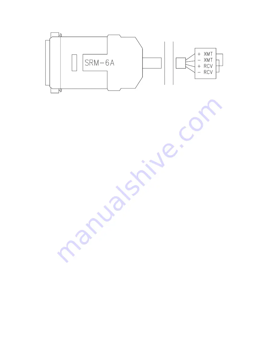
FIGURE 3.1-2 RAD Testing Datalogger End
1.
Disconnect the four conductor cables from
the SRM-6A RAD modem at the computer
end. Inside the SRM-6A, jumper the XMT +
to RCV + and jumper the XMT - to RCV -.
This creates a transmit loop which allows any
key pressed at the computer keyboard to be
seen on the screen. If the key pressed is not
seen, check the following: The COM port
configuration, the 25 pin cable from the
computer to the modem, and the SRM-6A
RAD modem Cable Test (Figure 3.1-1).
2.
Reconnect the 4 conductor cables to the
modem at the computer end, and disconnect
the cable from the modem at the datalogger
end. Twist the XMT + wire to RCV + wire,
twist the XMT - wire to RCV - wire. Repeat
the process of step 1 by pressing any key on
the computer keyboard. If the key pressed is
not displayed on the monitor, the cable
connections modem is defective and will need
to be repaired or replaced (Figure 3.1-2).
Modem at Datalogger Test
3.
If steps 1 and 2 pass, the modem at the
datalogger is suspect. Disconnect the modem
from the SC932, and bring the modem to the
computer site. Attach the modem to the
computer, and repeat step 1 by jumpering the
terminals of the modem, and pressing a key
on the computer keyboard.
4.
Replace the 9 pin cable from the datalogger
to the SC932 modem.
If the above tests pass and communication
to the datalogger still has not been
established, go to Sections 3.1 thru 3.3 to
test the datalogger. If the datalogger test
passes, then the SC932 is suspect and will
need to be repaired or replaced.
3.1.2 TESTING THE SC95C AND SC95A SHORT
HAUL MODEM, SYSTEMS SHIPPED BEFORE
JANUARY 1, 1991
A volt meter can be used to check the ring
signal from the calling modem. First,
disconnect the SC95C from the computer. Then
disconnect the wire from the SRC and RET
terminals. Connect the red + lead of the volt
meter to the SRC terminal and the black - lead
to the RET terminal. You should read about 9
volts. Press the ring button and hold it down.
The voltage should now go up to 15V. Release
the button and the voltage will go back down to
9V. This process may be repeated at the
answer modem end to make sure that the ring
signal is making it to the answer modem. This
is done by disconnecting the wires to the
answer modem, and connecting the red + and
black - volt meter leads to the SRC and RET
wires respectively.
If the above tests pass, and communication to
the datalogger still has not been established,
replace the 9 pin cable connected to the
datalogger and the SC95A. If all of the previous
tests pass, most likely the SC95A is damaged,
and will need to be repaired or replaced.
Using a Line Monitor
When unable to establish communication with
the weather station, a line monitor (also called a
"break out box") may be used to test
communications.
To help in observing the Transmit Data and
Receive Data lines, set the baud rate between
the computer and the weather station to 300 or
1200 baud.
Summary of Contents for NW8002
Page 12: ...1 7 FIGURE 1 4 1 NW8002 Cement Base FIGURE 1 4 2 NW8002 Tower with Tilt Base...
Page 34: ...A 1 APPENDIX A SENSOR SCHEMATICS...
Page 35: ...APPENDIX A SENSOR SCHEMATICS A 2...
Page 36: ...APPENDIX A SENSOR SCHEMATICS A 3...
Page 37: ...APPENDIX A SENSOR SCHEMATICS A 4...


