Appendix D. Distance vs. Antenna Gain, Terrain, and Other Factors
D-9
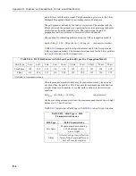
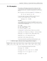
Fade margin = 154 – Lpath
Using the Lpath values from TABLE
, gives:
TABLE D-11. Fade Margin (dB) vs. Distance for 2-Ray Propagation Model in Example #2
Path Type
2 mi.
4 mi.
6 mi.
8 mi.
10 mi.
14 mi.
18 mi.
22 mi.
26 mi.
30 mi.
2-Ray
35
23
16
11
7
1
–3
–7
–10
–12
From TABLE
we see that this link should be very reliable up to a
distance of 8 miles and somewhat reliable at a distance of 10 miles. LOS
MAX
for this link is approximately 10.5 miles, so increasing antenna gain would not
provide much of an increase in distance. However, increasing antenna
elevation at one or both ends of the link could be beneficial.
Example #3
You need to run 125 ft of cable for the transmitter:
How much loss if I use LMR195 cable? 125 ft • (11.1 dB/100 ft) = 13.9 dB
How much loss if I use LMR400 cable? 125 ft • (3.9 dB/100 ft) = 4.9 dB
If I am using path loss from the 2-Ray model, and operating fine at 8 miles
with LMR195 cable, how much more fade margin could I expect if I use
LMR400 cable (assuming similar terrain and antenna elevations)?
13.9 dB – 4.9 dB => 9 dB more fade margin
Summary of Contents for RF451
Page 2: ......
Page 6: ......
Page 10: ...Table of Contents iv ...
Page 34: ...RF451 Spread Spectrum Radio 24 ...
Page 36: ......
Page 46: ...Appendix B Installation Scenarios B 10 ...
Page 58: ...Appendix D Distance vs Antenna Gain Terrain and Other Factors D 10 ...
Page 60: ......
Page 61: ......

