Appendix D. Distance vs. Antenna Gain, Terrain, and Other Factors
D-7
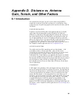
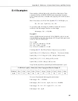
D.4 Examples
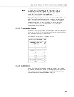
Some examples will help illustrate the trade-offs in a link analysis. These
examples will all use the RF451 900 MHz radio at maximum transmitter
power, 30 dB, and will use –108 dBm as the required power level at the radio
receiver.
Here’s the equation we will use, from Appendix
(p. D-2)
:
Ptx – Ltx + Gtx – Lpath + Grx – Lrx = Prx
As previously stated, the amount by which Prx exceeds the receiver’s
sensitivity is the fade margin. Therefore, in this example:
Fade margin = Prx – (–108 dBm)
Example #1
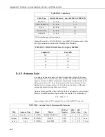
Antenex FG9023 antennas on each end, 20 ft of LMR195 cable on one end,
10 ft of LMR195 on the other end, antennas at 10 ft height, fairly open terrain
with a few trees. How far can I go?
Ptx = 30 dBm
Ltx = 20 ft • (11.1 dB/100 ft) = 2.22 dB
Gtx = Grx = 3 dBd = 5.15 dBi
Lrx = 10 ft • (11.1 dB/100 ft) = 1.11 dB
From Appendix
(p. D-5)
, we know:
Lpath (2-Ray) = 120 – 20log (h
tx
• h
rx
) + 40Log (d) (h in meters, d in km)
Lpath (2-Ray) = 120 – 20log (3.05 • 3.05) + 40Log (1.609 • d in mi)
Lpath (2-Ray) = 120 – 19.37 + 40Log (1.609 • d in mi)
Lpath (2-Ray) = 100.36 + 40Log (1.609 • d in mi)
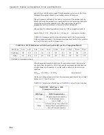
Using the above equation to calculate Lpath at different distances, gives:
TABLE D-8. Lpath vs. Distance for 2-Ray Propagation Model in Example #1
Distance 2 mi.
4 mi.
6 mi.
8 mi.
10 mi.
14 mi.
18 mi.
22 mi.
26 mi.
30 mi.
Lpath
121
133
140
145
149
155
159
162
165
168
Now we will calculate the fade margin for each distance:
Fade margin = Prx – (–108 dBm)
Fade margin = Ptx – Ltx + Gtx – Lpath + Grx – Lrx + 108 dBM
Fade margin = 30 – 2.22 + 5.15 – Lpath +5.15 – 1.11 + 108
Fade margin = 145 – Lpath
Summary of Contents for RF451
Page 2: ......
Page 6: ......
Page 10: ...Table of Contents iv ...
Page 34: ...RF451 Spread Spectrum Radio 24 ...
Page 36: ......
Page 46: ...Appendix B Installation Scenarios B 10 ...
Page 58: ...Appendix D Distance vs Antenna Gain Terrain and Other Factors D 10 ...
Page 60: ......
Page 61: ......


