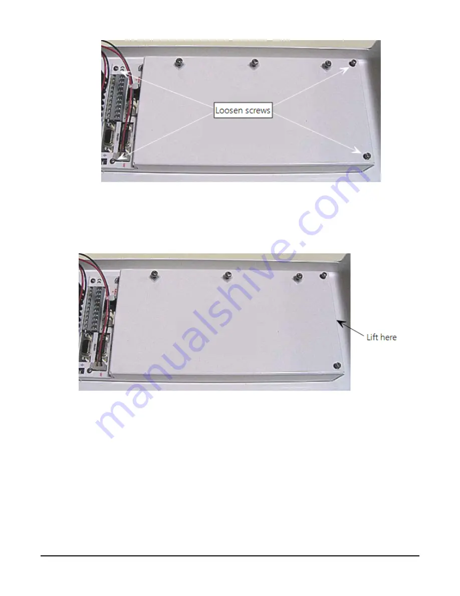
FIGURE 6-13. Screws that secure the electronics cover
4. Remove the electronics cover to expose the printed circuit board (PCB) (
27)).
FIGURE 6-14. Removal of the electronics cover
5. Move the jumper at the top of the PCB so that it is placed over the center and right pins
(
Section 6. Installation
27


