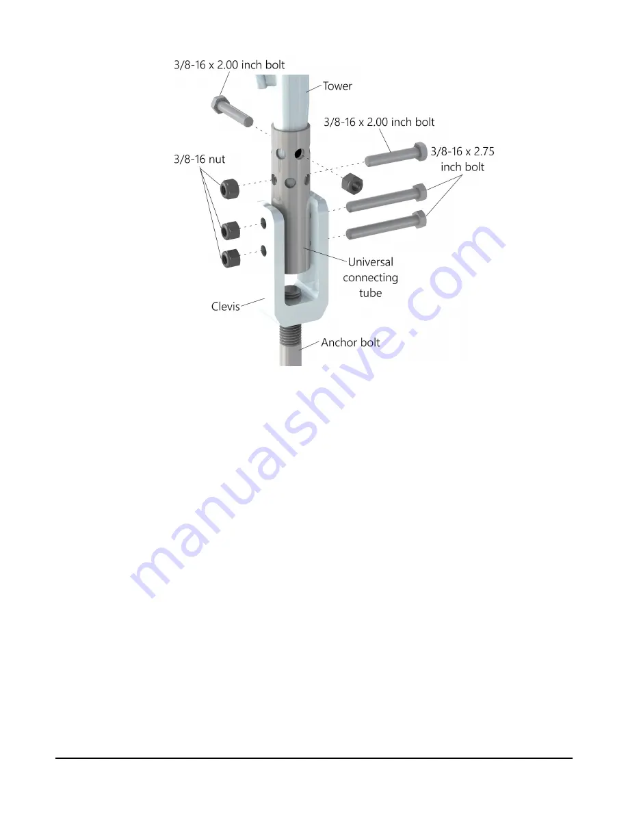
FIGURE 7-10. Tower clevis assembly
10. With the help of a second person, lower the bottom section of the tower into the three
universal connecting tubes. Secure the tower section to the tubes with two 3/8-16 x 2-inch
bolts and two locknuts per tower leg. (
11. Using a carpenter’s level, ensure the tower section is plumb. If the tower is not plum,
choose which leg needs to be adjusted and have a second person support the tower
section while adjusting the clevis for that leg.
a. Remove both 3/8-16 x 2.75-inch bolts.
b. Turn the clevis clockwise to lower the leg and counterclockwise to raise the leg.
c. Reinsert the two 3/8-16 x 2.75-inch bolts and finger-tighten the nuts.
d. Check the tower section again to see if it is plum. If not, repeat steps a through c to
refine the tower position as needed.
e. Reattach the 3/8-16 x 2.75-inch bolts and locknuts on legs 2 and 3 (
19)).
UT20 and UT30 Universal Towers
19
Summary of Contents for UT20
Page 1: ...Revision 03 2020 Copyright 1993 2020 Campbell Scientific Inc...
Page 10: ...FIGURE 5 1 UT20 tower UT20 and UT30 Universal Towers 7...
Page 38: ...FIGURE 7 28 Bracket selection UT20 and UT30 Universal Towers 35...
Page 41: ...A B 14 7 Page 1 of 3 A A B B C C 1 2 3 0 1 2 3 3 inch reference...
Page 42: ...C 43 2 cm 17 in A UTBASE Page 2 of 3 A A B B C C 1 2 3 0 1 2 3 3 inch reference...
Page 43: ...C B UTBASE Page 3 of 3 A A B B C C 1 2 3 0 1 2 3 3 inch reference...


