GB
7
913
POSITIONING AND INSTALLING THE APPLIANCE
2b
2a
2c
2b2
2d
1 Once the appliance has been unpacked, check that the mains voltage is the same as that indicated on the rating
plate.
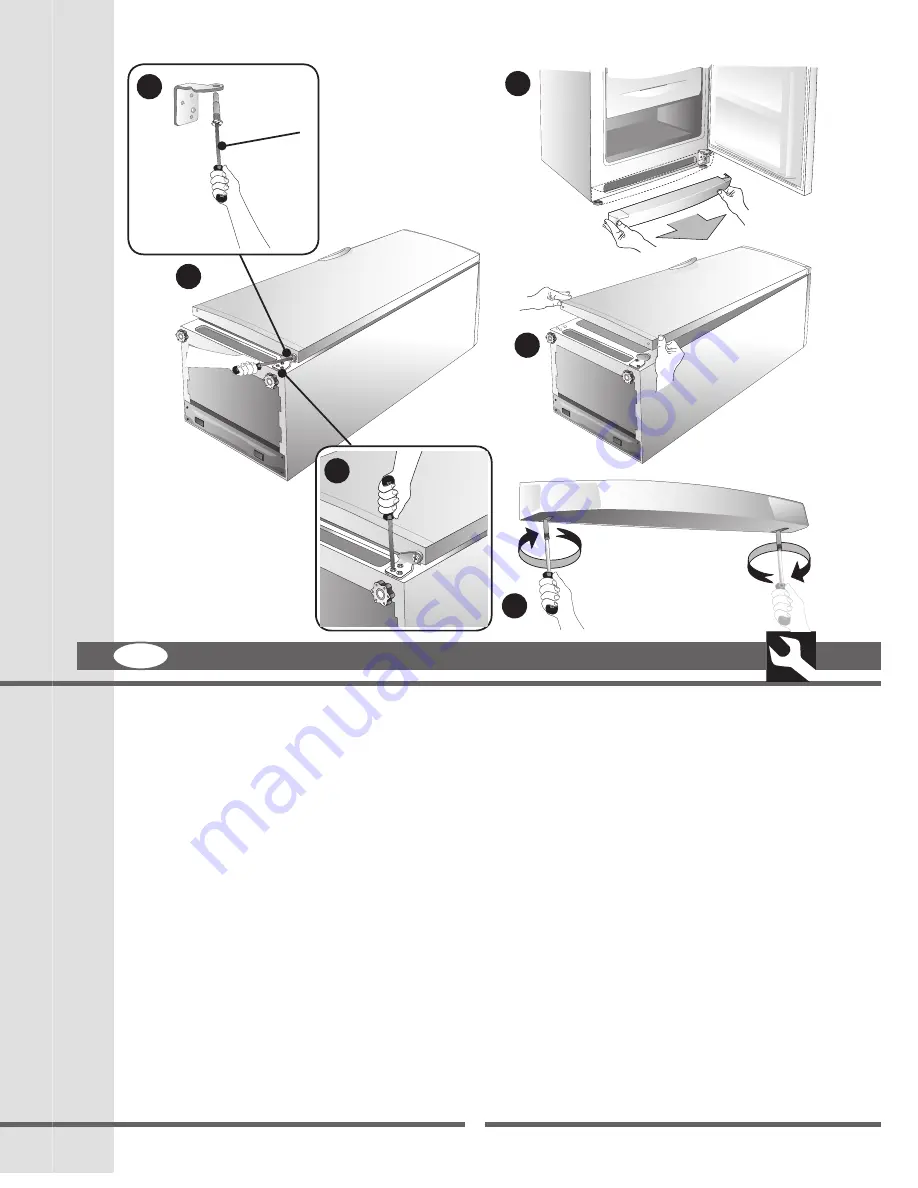
2 If the door opening direction is as required, go to Point
3 Otherwise, reverse the position of the hinges.
To do this, carefully place the appliance on its back. Use spacers to prevent crushing the condenser pipes and
damaging the compressor unit.
2a Remove the plinth by pulling it.
2b Remove the lower hinge and unscrew pin (A).
2c Remove the door by pulling downwards.
2d Unscrew the upper pin and screw it in on the opposite side.
A
2b3
Summary of Contents for FRZ360N
Page 25: ...913 ...
Page 26: ...913 ...
Page 27: ...913 ...
Page 28: ...913 1 ...
Page 29: ...913 ...
Page 30: ...913 A Fig h S3 ...
Page 31: ...913 Fig e Fig f Fig g T2 S2 T2 S2 T1 S1 T1 S1 S3 ...
Page 32: ...913 T3 S3 Fig a Fig b Fig c Fig d T3 S3 S3 ...
Page 33: ...913 T2 T3 T1 S1 S2 S3 S4 Fig 2 Fig 1 ...
Page 34: ...913 A Fig i S2 S4 S2 S4 T2 ...
Page 35: ...913 Fig h T2 S2 ...
Page 36: ...913 Fig e Fig f T3 S3 T3 S3 T1 S1 T1 S1 Fig g Fig h S5 T2 S2 ...
Page 37: ...913 T4 S5 Fig a Fig b Fig c Fig d T4 S5 S5 ...
Page 38: ...913 S1 S2 S3 S4 S5 T1 T2 T3 T4 Fig 1 Fig 2 ...
Page 39: ...913 Green and Yellow to Earth Blue to Neutral 13 amp Fuse Brown to Live Cord Clamp ...
Page 40: ...913 3 I ...
Page 41: ...913 2e 2g 2n 2h 2p 2f ...
Page 42: ...913 2b 2a 2c 2b2 2d A 2b3 ...
Page 43: ...913 1 ...
Page 44: ...913 5 6 8 9 7 1 2 3 4 1 2 3 4 Mod A Mod B ...
Page 45: ...913 ...
Page 46: ...913 Mod A Mod B ...
Page 47: ...913 Mod A Mod B ...


