6
7
Technical data
DANE
AUDIO-WIDEO
Frequency
869 MHz
5 .8 GHz
Number of operating channels
10
8/16*
Radio link modulation
GFSK
FM
EIRP radiated power
300 mW
25 mW
Receiver sensitivity
−118 dBm@1200 bps /
−114 dBm@9600 bps
≤ −85 dBm
Antenna connectors
SMA-RP F 50 Ω
SMA-RP F 50 Ω
Antenna characteristics
omnidirectional
360°H/15°V
Tx: directional –
30°H/30°V
Rx: directional –
20°H/20°V
Antenna gain
2.15 dBi
Tx: 5 dBi; Rx: 19 dBi
Device range
3 km (with the option to extend the range to 5 km)
Video interface
BNC 1Vp-p (75 Ω) + screw terminal for UTP (100 Ω)
Video format
PAL/NTSC
Audio interface
Screw terminal, stereo audio in/out 2Vp-p (2 kΩ)
Audio frequency response
50–15000 Hz
Data interface
RS-485 (A+, B−)
Supported protocols
Alec, Aritech, Baxal, Bosch Biphase (with additional
converter), COP-1, COP-2, D-Max, Dynacolor, Ganz,
Kalatel, LG, Longcomity, Molynx, Multix, Panasonic,
Pelco D, Pelco P, Samsung, Santachi, Sensormatic,
Ultrak, VCL, Vicon and many other
Data format
8n1, 8o1, 8e1
Data transmission rate
1200, 2400, 4800, 9600, 19200 [bps]
Power supply voltage
9–14 V**
Maximum power consumption
310 mA**
Case protection class
IP65 (external application)
Operating temperature
from −20°C to +55°C
Warranty
2 years
Certificates
CE
Device external dimensions
Tx: 152 × 103 × 60 [mm]; Rx: 164 × 164 × 80 [mm]
*The number of usable channels depends on the regulations in the specific country. The
use of 8 channels is permitted in the European Union countries, while in many countries
outside of the Union 16 channels can be used.
**We recommend using high quality power supplies (high-efficiency transformer-based
or impulse ones, with low current rippling), with current efficiency of at least 400 mA
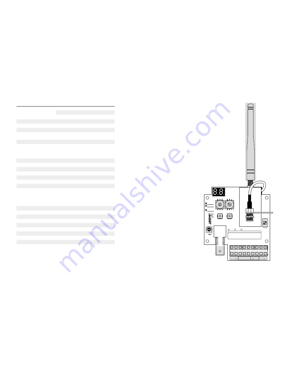
[A] - 869 MHz antenna
[B] - LED display
[C] - POWER diode
[D] - LINK diode
[E] - diode signalling data transmission
[F] - rotary switch for setting
video channels
[G] - rotary switch for setting data channels
[H] - SET button
[I] - ENTER button
[J] - on/off switch for the 120 Ω
terminator on the RS-485 line
[K] -
changing the operating frequency band
[L] - adjusting the video signal level
The video signal can be connected through:
[M] - video coaxial cable
[N] - UTP twisted pair cable
[O] - audio signals connector
[P] - RS-485 signals
connector
[R] - +12 V DC
power supply
7
6
5
4 3 2 1
0
9
8
A9
8 7
6 5 4 3
2
1
0F
E
D
C
B
ON
1 2
VIDEO CH.
SET
ENTER
BNC VIDEO
V-Reg
DATA CH.
CH
ANNE
LS
PWR
T×D
R×D
LINK
UTP VIDEO
AUDIO
RS485
SUPPLY
-
A
L
B-
R
GND
GND
12
WIRELESS VIDEO & TELEMETRY
BASIC:
F1 - baud rate set | F2 - data format set
ADVANCED: F3 - pairing | F4 - video channel set
F5 - testing | F6 - remove TXs (RX only)
MENU
TERM
1
20
Ω
ON
/OF
F
O
FF - E
U
O
N - n
on E
U
CAM-9
w
w
w
.c
am
sa
t.c
om
RX-M
RX-S
TX
-
A
B
C
D
E
F
G
I
H
JK
L
M
N
O
P
R


