background image

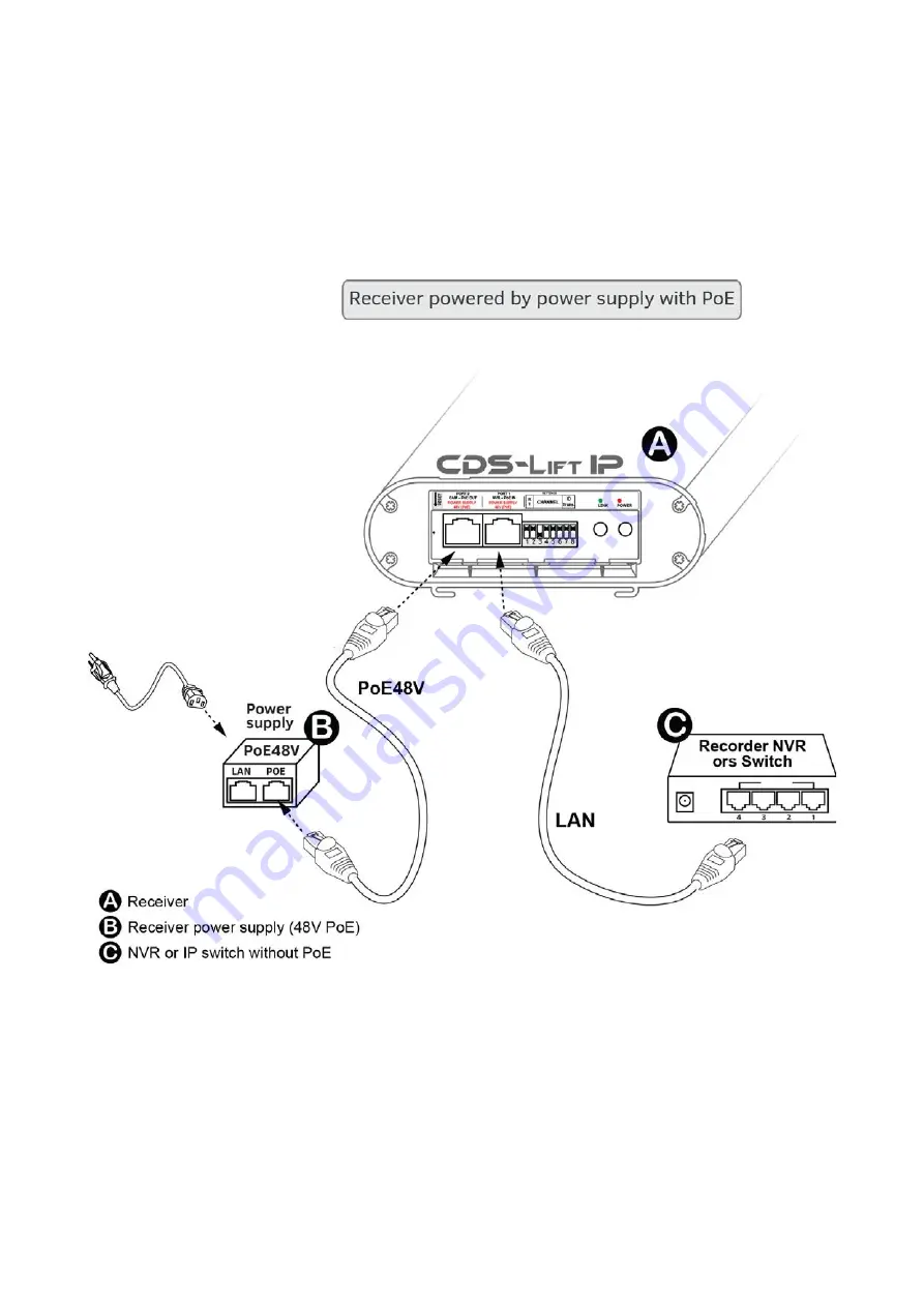
The receiver (NVR side)
The receiver can be powered from a PoE injector or NVR PoE switch or PoE network.

Set dipswitch No. 1 to ON mode (receiver), set the operating channel by a table 

identical to the transmitter, set DIP7 and DIP8 ON (up)

Connect NVR by the network cable to the PORT 1 or LAN port PoE in power supply.

Connect power source for example included PoE48V to PORT 2. To this port you 

can also connect NVR with PoE or PoE network switch.

Summary of Contents for CDS-LIFT IP

Page 1: ...User s manual ver 1 3 System for transmission of video and audio from IP cameras in the elevators www camsat com ...

Page 2: ... render the warranty null and void The device has passed through the mandatory compliance assessment and it meets basic requirements in the European New Approach Directives The product is CE marked The device is designed to work within the European Union and beyond Always adhere to the rules and regulations applicable in each country The device has the ability to work with the power and frequency ...

Page 3: ...bles and the cables between it and other devices if the device is transferred to a room where the temperature is higher than where it has previously been kept water vapour may condensate inside its casing which will prevent its proper use Wait until the condensed water evaporates Interference The transmission distance may vary depending on the frequency environment ra dio waves buildings weather c...

Page 4: ...ll data transparently regardless of IP cameras and recorders It works on both the Point to Point and Point to Multipoint receiving the signal from 4 transmitters on two elevators output power of 23dBm at 5GHz band operation built in dual antenna MIMO 2 x 5 GHz 14 dBi range 500m LoS outer casing IP55 operating temperature from 20 C to 55 C Contents of the package CDS LiftIP x 1 pc PoE power supply ...

Page 5: ...signals can be obtained by logging on to the users panel website POWER red LED for power status Preparation for operation It is recommended that the first start up and configura tion of the system is made on the desk at small dis tances This can save a lot of valuable time with the configuration of many different cameras on the ob ject Function SETTINGS Operating mode Receiver Transmitter Operatin...

Page 6: ...IP can be connected in a point to multipoint configuration You can connect the device from several elevators to one receiver For such an application you should provide optical visibility between each transmitter and the receiver These settings are configured by switches 7 and 8 in each transmitter according to the following formula After 90 seconds since power on unit will establish interconnectio...

Page 7: ......

Page 8: ...d 90 degrees relative to each other as this will result in incompatibility of polarized antennas Do not install the devices at distances of less than 0 5 m from each other It is recommended to use a minimum distance of 1m Install receiver and antenna directed exactly to the transmitting point Set the desired operating channel according to the table Channel numbers and polarity of antennas should b...

Page 9: ...ferent cameras Transmitter IP camera side Set dipswitch 1 to OFF mode transmitter set the operating channel according to the table set the number of transmitter if there is more than one transmitter connect IP camera with a network cable with RJ45 PORT 2 connect included power supply PoE48V to PORT 1 connect the second camera by the network cable to the RJ45 LAN input in the power supply of the tr...

Page 10: ...o 1 to ON mode receiver set the operating channel by a table identical to the transmitter set DIP7 and DIP8 ON up Connect NVR by the network cable to the PORT 1 or LAN port PoE in power supply Connect power source for example included PoE48V to PORT 2 To this port you can also connect NVR with PoE or PoE network switch ...

Page 11: ...Application examples ...

Page 12: ......

Page 13: ... to their purpose CE Europe FCC US Using other frequencies depends on the legal regu lations of the country where you are If you are not sure about regulations in your country consult your supplier WARNING The device can operate at a frequency range and power that can be charged or completely prohibited in your area or your country ...

Page 14: ... need to be imported the repair deadline may be extended After the repairs have been carried out the warranty period will be extended by the repair time 7 The warrantor may refuse to carry out warranty repairs or terminate the warranty if it is determined that the seals placed on devices or components comprising it are damaged The warranty does not cover 1 Mechanical damage of devices and failures...

Page 15: ......

Page 16: ... presented to the left informs that this electrical or elec tronicdevice after its use has ended cannot be thrown together withhousehold refuse The device should be delivered to a specia lisedcollection point Detailed information about the closest col lection pointis available from local authorities The proper disposal of this device allows for preserving precious resources and avo idingthe negati...

Reviews: