6
ADJUSTMENTS
TRACK TENSION
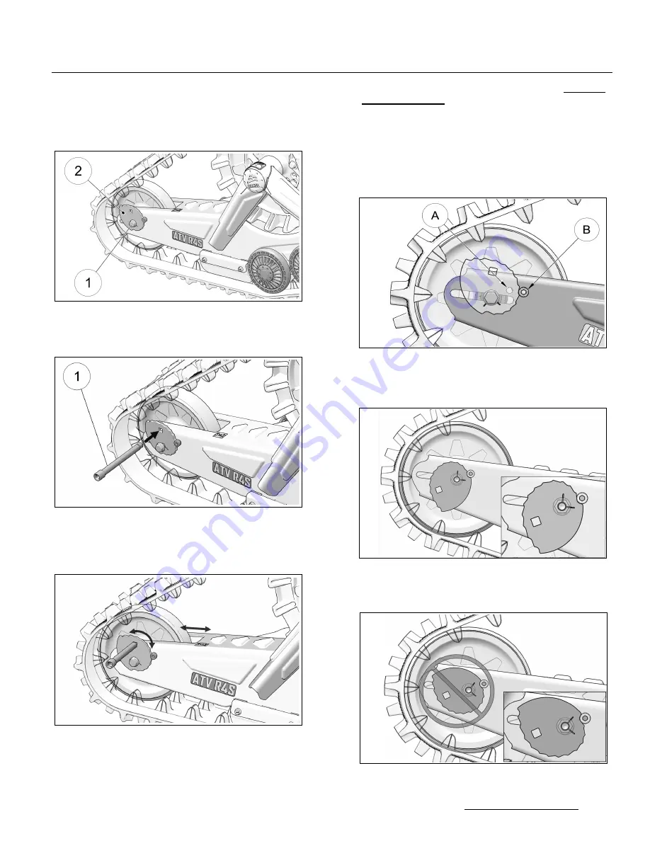
• Loosen both tensioner side wheel shaft bolts
(
1
), enough to allow tensioner cams (
2
) to turn.
Figure 24
• Insert ratchet wrench extension with 3/8” drive
(
1
) in tensioner cam’s square hole. Figure 25.
Figure 25
• Turn cam on each side and adjust tension as
close as possible to the recommended
tension. Figure 26.
Figure 26
CAUTION: Tensioner cam adjustment position
must identical on both sides of Track System.
Verify adjustment by counting at which position
each cam is set. Both positions must be the same.
• After having adjusted the tension and
verified
cam positions
, re-tighten both wheel shaft
bolts to 50 N-m (37 lb-ft) of torque.
• Position of Tensioner cam locking bolts:
(
A
) - System with 15 or 16-tooth sprockets.
(
B
) - System with 17 or 18-tooth sprockets. See
Figure 27
• Installation direction of Tensioner cams. Figure
29 and Figure 29.
Figure 28
NOTE: With tensioner cam in position 0, the small
slots cut at 90
o
should indicate 3 o’clock.
Figure 29
Correct
Wrong


