background image


CPS-i3000(R2) MANUAL 

Camtec Power Supplies GmbH  -  Gewerbestrasse 30  -  DE-76327  Pfinztal / Germany   

P.14/22 (04/2016.01.5) 

Tel. +49 (721) 46596 - 0  Fax +49 (721) 46596 - 77    

www.camtec-gmbh.com

   -   

info@camtec-gmbh.com


(Subject to alterations. This product is not designed to be used in applications such as life support systems wherein a failure or malfunction could result in injury or death) 


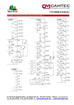
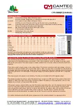
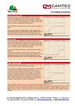
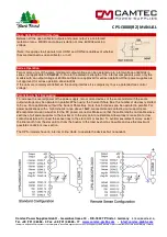
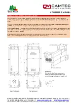
C/V Chart and Operating Point 

The output voltage set Vout is always linear proportional to the control signal 
Ureg. 
 
The desired control signal is selected via the DIP switcher:  
0-5V, 0-10V, 0-20mA oder 4-20mA.  
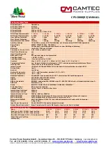


Model 

Value UA1 (V) 

Value IA1 (A) 

Value UA2 (V) 

Value IA2 (A) 

Pmax (IA1/IA2) 

CPS-i3000.018 

18Vdc 

150A 

14,4Vdc 

185A 

2700/2664W 

CPS-i3000.030 

30Vdc 

100A 

24Vdc 

125A 

3000/3000W


CPS-i3000.060 

60Vdc 

50A 

48Vdc 

62,5A 

3000/3000W


CPS-i3000.090 

90Vdc 

33,3A 

72Vdc 

41,5A 

2997/2988W


CPS-i3000.150 

150Vdc 

20A 

120Vdc 

25A 

3000/3000W


CPS-i3000.300 

300Vdc 

10A 

240Vdc 

12,5A 

3000/3000W


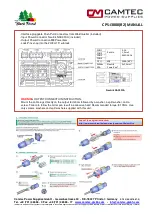
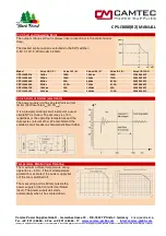
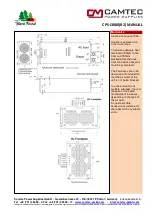
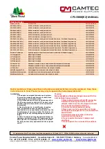
Inrush Current Limiter (electronic) 

The power supply unit has an electronic current 
limiter (230Vac=14,6A

rms

/20,7A

peak

).  

 
It is a precisely working circuit instead of a usual 
simple NTC solution. The accuracy is ±10%, 
regardless of the operating temperature and the 
duty cycles (interval 

10s). We recommend the 

smallest circuit breaker a characteristic B with 25A. 


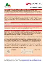
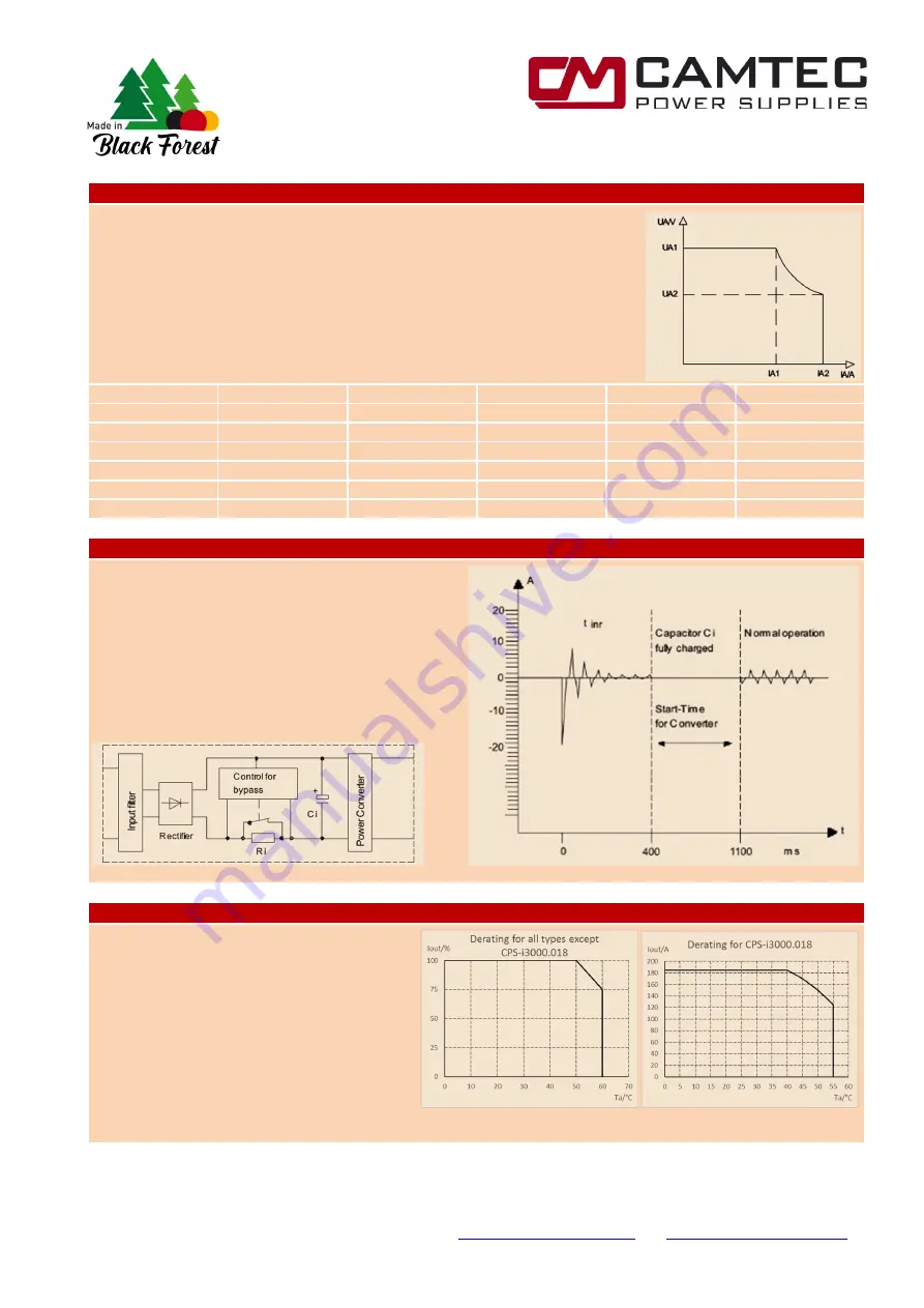
Temperature Monitoring & Derating 

The maximum ambient temperature during 
operation is + 60°C. If the overtemperature 
protection is activated, the power supply but 
not the fan is switched off. 
 
The measuring point is 50mm outside the 
power supply at the front side (fan/blower 
input). The power supply unit starts 
automatically when it has cooled down. 


Summary of Contents for 3041107001CA

Page 1: ...rogramming Real time I V monitoring Reference voltage f autonomous programming CSB Current Share Bus Inhibit for safe interlocking Remote Shutdown Remote Shutdown Power Good Relay AC ok and DC ok Precise dynamics on load change Series parallel operation up to 100kW EMC conducted class B radiated class A Efficiency 92 94 PFC Powerfactor 0 99 Variable controlled fans from Papst Long lifetime under h...

Page 2: ...ign specifications call for the highest standards of safety and interference suppression The device was developed in accordance with the requirements of EN61010 1 EN61010 2 201 EN62368 1 and the EMC standards EN55032 conducted Class B radiated Class A The mechanical design of the CPS i3000 device series is unique It is the first power supply line in the world market which can be flexibly adapted t...

Page 3: ... no ticker operation Master Slave Mode Ureg OUT Ireg OUT The master slave mode can be defined in the parallel operation One device can be set as the master the other involved network units act as a slave and the setting signals follow current voltage which are commanded by the Master This ensures that all devices are operated synchronously Current Share Bus CS In parallel operation the involved ne...

Page 4: ...measuring point distance 10mm Hold Up Time 20ms 230Vac mains buffering at full load Inrush Current 14 6Aeff 20 7Apeak 230Vac active electronic inrush protection no simple NTC Startup Delay typ 1s Softstart typ 100ms Ambient Temperature 20 C 60 C operating derating 2 5 C 50 C Storage Temperature 40 C 85 C Ambient Conditions Humidity 95 non condensing 25 C climate class 3K3 pollution degree 2 ROHS 2...

Page 5: ...Inhibit Active Open Collector 9 OT Output Signal Over Temperature Open Collector 10 TA Output Signal Temperature Alarm Open Collector Early warning 11 OCP Output Signal Over Current Protection Open Collector 12 CC Output Signal Constant Current Mode Open Collector 13 OVP Output Signal Over Voltage Open Collector 14 CV Output Signal Constant Voltage Mode Open Collector Analogue Interface CON3 Conne...

Page 6: ...Tel 49 721 46596 0 Fax 49 721 46596 77 www camtec gmbh com info camtec gmbh com Subject to alterations This product is not designed to be used in applications such as life support systems wherein a failure or malfunction could result in injury or death Schematic of the internal circuits analogue interface CON1 4 ...

Page 7: ...0 C 250Vac 20A Neutrik PowerCon 3x2 5 mm Neutrik NAC3FCA Copy of the original instruction http www neutrik com de powercon powercon 20 a nac3fca Interface pluggable Push Pull Connectors from Weidmueller included Input Power Connector Neutrik NAC3FCA included Output Power Connection M8 Powerbars Lock Pins snap into the 2U 3U 19 subrack WARNING OUTPUT CONNECTION INSTRUCTION Mount the cable lugs dire...

Page 8: ...eries is an analog interface The output voltage is linearly proportional to the adjusted analog control signal If the control signal 0V and or 0A applies the power supply delivers 0V at the output The power supply is already working from 0V output voltage and low load with high precision The monitor signal is analog linear to the output voltage The monitor signal for current and voltage is the rea...

Page 9: ...current to the output This special behaviour is a protection for the power supply and for the connected load Compensation of Load Line Drop Voltage Sense standard operation mode The CPS i power supply has a Sense Mode to compensate for the voltage drop over long load lines The compensation amounts to a maximum of 2V per load line Under certain circumstances it can be expected to apply more complic...

Page 10: ...ribution in parallel operation of several identical CPS i units Define the power supply as the master which you want to address with your control A coding of the power modules as the master or the slave is required see below table The signals of the interface are looped together Connect Ureg OUT and Ireg OUT of the master to Ureg IN and Ireg IN from to slave Connect the corresponding Ureg OUT Ireg...

Page 11: ...lternatively a voltage of 10 to 30V typ 12V 1 5mA 24V 5 5mA can be applied If the standby repeals the power supply starts with a delay of 500ms Using the soft start the current and the voltage rises within 100ms continuously to the default set values Between control input SB and power output is a reinforced isolation of max 400Vdc and a basic isolation of max 600Vdc working voltage Inhibit Interlo...

Page 12: ...ay contacts changeover The contacts of CON1 Pin1 and CON1 Pin3 are closed relay coil is energized when the input voltage is higher than typ 175Vac or 210Vdc switch on The contacts of CON1 Pin5 and CON1 Pin3 are closed relay coil is not energized when the input voltage is lower than typical 165Vac or 145Vdc turn off Contact load resistive load 30Vdc 1A 60Vdc 0 3A 30Vac 0 5A Between the relay contac...

Page 13: ...etween the TEMP signal and power output is a reinforced isolation of max 400Vdc and a basic isolation of max 600Vdc working voltage Temperature Control Signal PSOT of the PowerSink Fast Down Programming Option The PowerSink option has a temperature monitor The alarm signal PSOT is high when the internal PowerSink module is overheated Output Open Collector IMAX 10mA VLOW 0 6V VMAX 30V If PSOT is ac...

Page 14: ...00A 24Vdc 125A 3000 3000W CPS i3000 060 60Vdc 50A 48Vdc 62 5A 3000 3000W CPS i3000 090 90Vdc 33 3A 72Vdc 41 5A 2997 2988W CPS i3000 150 150Vdc 20A 120Vdc 25A 3000 3000W CPS i3000 300 300Vdc 10A 240Vdc 12 5A 3000 3000W Inrush Current Limiter electronic The power supply unit has an electronic current limiter 230Vac 14 6Arms 20 7Apeak It is a precisely working circuit instead of a usual simple NTC so...

Page 15: ...ther power supplies are not approved for series operation above 60Vdc If the units are remotely controlled via the analog interface it is compulsory to use a potential free control voltage Paralleling N 1 Decoupling To increase the overall power of the power supply two or more devices of the same model with the same output voltage may be operated in parallel When using the Current Share Bus the nu...

Page 16: ...l Germany P 16 22 04 2016 01 5 Tel 49 721 46596 0 Fax 49 721 46596 77 www camtec gmbh com info camtec gmbh com Subject to alterations This product is not designed to be used in applications such as life support systems wherein a failure or malfunction could result in injury or death ...

Page 17: ...al Safety Factory Test Field Test Owner 60Vdc 2800Vdc Type and factory test are the manufacturer While repating damage can happen to the power supply unit For the field test owner follow the below instruction a Use suitable test equipment raising the voltage slowly b Short circuit L1 and N and all the DC output terminals c Use only test voltages of 50 60Hz The outputs are unearthed and therefore t...

Page 18: ...esult in injury or death Mechanics Aluminium housing IP20 Cooling is achieved via front to rear fans To ensure adequate heat dissipation 50mm to the front and 150mm blockade free distance from the device back wall must be guaranteed The harnesses are to be designed and installed to that the air outlet of the unit is not being blocked In a rack mounting of multiple subracks the rear distance of the...

Page 19: ...electronic current sink is used the output voltage remains constant at the set value The current sink provides fast dynamic response Fig 1 Fig 2 Fig 3 A Power Sink see Fig 1 enables fast down programming at low load conditions or without a load For comparison see Figure 2 without and Figure 3 with PS option When paralleling the power supplies the SD SB and INH need to be connected in parallel to a...

Page 20: ...www camtec gmbh com info camtec gmbh com Subject to alterations This product is not designed to be used in applications such as life support systems wherein a failure or malfunction could result in injury or death 19 Subrack 2U 3U 2U Subrack for 1 3 CPS i3000 with up to 9kW continuous power 3U Subrack for 1 5 CPS i3000 with up to 15kW continuous power ...

Page 21: ... to custom design power supplies Steplessly hard mount of the CPS i2000 3000 power supply modules in a 3D room In practice that means that one can mount the modules into every angle imaginable Our 3D Heat Dissipation 3D HD ensures optimal cooling in each mounting position you may consider All you may consider is to make sure that at least a distance of 5cm 2 Inch to the front cooling slots and 15c...

Page 22: ... 3U 5 Modules mountable only in conjunction with front panel 3U orderable 2201005001CA 19 Rack Rail 2x Support Rails for rack mount mounting kit included 2201008001CA Cable Management Rail Cable support for rack mount mounting kit included In preparation Hard Mount Holder narrow 2x Holder for strait wall mount mounting kit included 2201011001CA Hard Mount Holder flat 2x Holder for flat wall mount ...

Reviews: