7
4.4
– Digital Output Wiring
The controller mounted on the DynaFLO is equipped with
two digital relay outputs that are programmed to open and
close in relation to alarms. O0 (Output0) and O1 (Output1)
could be located on the bottom of the controller. O0 is
intended to be used for closing a circuit that energizes an
alarm lamp or indicator. This contact will continuously open
and close if there is an active unacknowledged alarm,
remains closed whenever there is an acknowledged active
alarm and opens whenever there are no alarms. More
details about alarms are explained in section 5.2.2.
O1 on the other side is intended to be used with remote
systems such as a BMS (Building Management System), or
a building alarm panel as this contact is either continuously
ON whenever there is an active alarm (regardless of
acknowledged or not) or continuously OFF whenever there
are no alarms. This is to protect other contacts or electrical
systems that might be present in a remote system circuit.
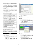
The electrical specifications of the relays can be seen
below:
Depending on the type of load and circuit that O0 and/or O1
are intended to switch ON and OFF, power up to either
30VDC MAX. or 250VAC MAX. needs to be provided to
terminal 15 as shown in the next figure while conforming to
electrical specifications in the above table. More details
about the wiring can be seen in Appendix B.
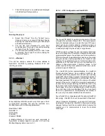
Increasing Contact Life Span:
To increase the life span of the relay output contacts and
protect the device from potential damage by reverse EMF,
connect:
A clamping diode in parallel with each inductive
DC load.
An RC snubber circuit in parallel with each
inductive AC load.


