14
IMPORTANT
Upon completion of initial installation or following any repair
work on the gas system, leak test all gas connections with a
soap solution while the main burner is firing. Immediately
repair any leak found in the gas train or related components.
DO NOT operate an appliance with a leak in the gas train,
valves or related gas piping.
3.5
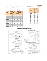
HIGH and LOW GAS PRESSURE SWITCHES
(Optional)
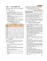
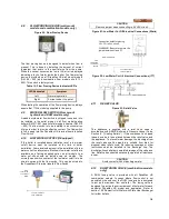
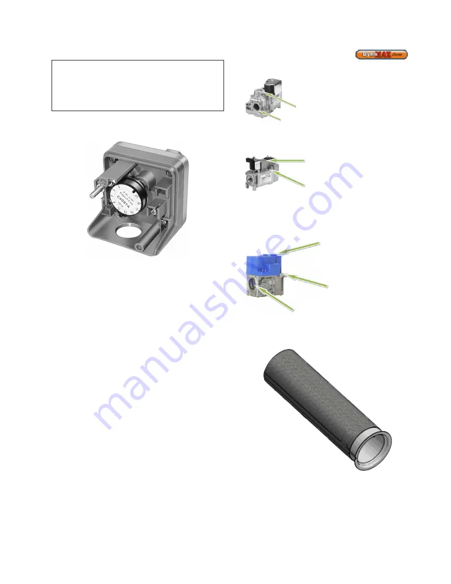
Figure 14: Low gas pressure switch (cover removed)
High and low gas pressure switches are available as an
option and are wired in series with the normally closed
blocked flue switch. The high gas pressure switch is used to
monitor the gas pressure at the outlet of the control valve. If
gas pressure exceeds the maximum setting of the pressure
switch, the appliance will shut down and an ILK OFF
message will be indicated on the display. The low gas
pressure switch is to monitor the minimum incoming gas
supply pressure supplied to the gas train. If gas pressure
falls below the minimum setting of the pressure switch, the
appliance will shut down and an ILK OFF message will be
displayed.
3.6
AIR/GAS RATIO VALVE
The main gas valve supplying gas to the burner on this
appliance utilizes a servo pressure regulator providing a
slow opening, fast closing safety shut off and air/gas ratio
control for the gas combustion process. The valve is a 1:1
negative pressure gas valve. The valve performs the
functions of a pressure regulator, safety shutoff, and air/gas
ratio control. Full closing of the valve seat occurs in less than
0.8 seconds when the valve is de-energized. Operation of
the gas valve in combination with the combustion air fan
allows the burner input rate to vary from 20% to 100% based
on temperature demand. The inlet gas supply pressure must
be maintained within the specified minimum and maximum
pressures as indicated in Table 9.
The air/gas ratio is preset at the factory and adjustment is
not usually required if gas supply pressure is maintained
within the specified range. There are no serviceable parts on
the air/gas ratio valve control.
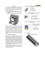
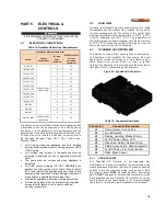
Figure 15: DynaMax HS 80 – 250, 260 1:1 Air/Gas Ratio
Control Valve
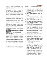
Figure 16: DynaMax HS 299 – 399 1:1 Air/Gas Ratio
Control Valve
Figure 17: DynaMax HS 500 – 800 1:1 Air/Gas Ratio
Control Valve
3.7
BURNER
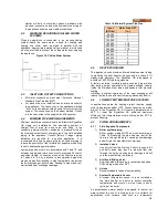
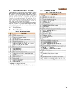
Figure 18: DynaMax HS Burner
Low-fire air/gas ratio
adjustment, use slotted
screwdriver for adjustment,
clockwise increases CO
2
High fire adjustment:
use throttle screw
located on venturi
Low fire adjustment screw Torx
40 clockwise increases CO
2
Gas Inlet
Low-fire air gas ratio adjustment
(use Torx 40 for adjustment
clockwise increases CO
2
)
High-fire air gas ratio adjustment (Use
slotted screwdriver for adjustment,
counter-clockwise increases CO
2
)
Lift top cover to access high fire
air/gas ratio adjustment (use 3mm
allen key for adjustment, counter-
clockwise increases CO
2)
Gas Inlet
Summary of Contents for DynaMax DMH081
Page 2: ......
Page 68: ...65 PART 14 EXPLODED VIEW PARTS LIST DYNAMAX HS WALL HUNG...
Page 69: ...66 DYNAMAX HS FLOOR MOUNT...
Page 76: ...73 PART 15 ELECTRICAL DIAGRAMS 15 1 DM 80 299 INTERNAL WIRING DIAGRAM...
Page 77: ...74 15 2 DM 399 800 INTERNAL WIRING DIAGRAM...
Page 78: ...75...

